advertisement


Balanced tonearm connections - a few questions.

InSides

dŵr
This will be a longish intro, but bear with me please.

Introduction

A few months ago acquired a few components to finish up my headphone system, including both a SL-1210MK7 and a Elac PPA-2, as discussed here.

The PPA-2 has, among other options, a balanced input option, in addition to the balanced output option. The headphone amp is fully balanced, as are all my headphones. With cartridges being inherently balanced, I thought it might be a good idea to do a fully balanced chain, transducer-to-transducer.

Now, there are multiple kits to convert an SL12xx deck to balanced output, most common the one from PrecisionSoundLab and the jack plate from KAB. But those kits work all the way to MK6 or the G/GR decks due to the shape of the base plate and included cutouts.

No luck for the MK7.

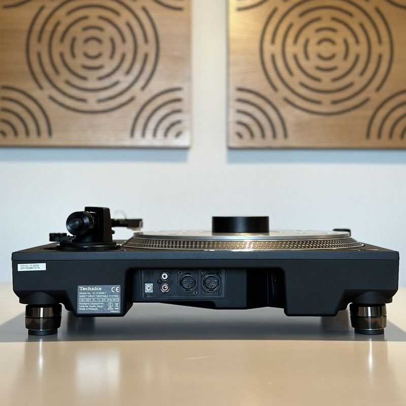
So I went a different route noticing that the plastic jack plate on the back of the SL-12xxMK7 has quite some blank space. This space is there in order to accomodate the additional output RCA's for the built in phono with some models (think SL-1500C), but on the MK7 it is blank. They I tried multiple online vendors of spare parts and was finally able to secure a blank jack plate with Green-Vinyl, as decsribed here.

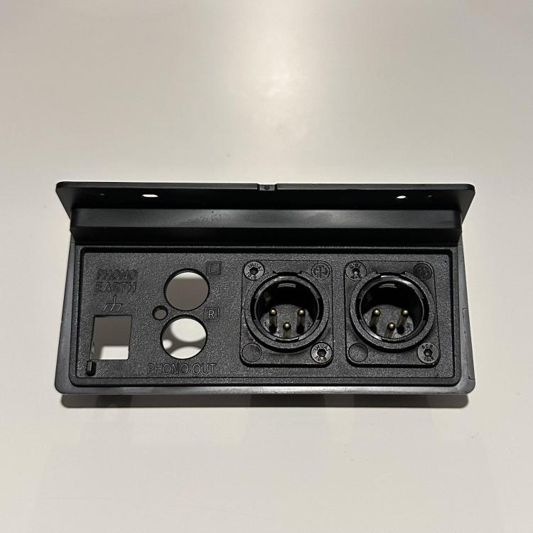
It took a while, but I have the jack plate, and had it drilled to accept two Neutrik XLR connectors, making it look to me as if they always belonged there:

viber-image-2023-01-11-22-08-43-584-thumb-jpg-dc7c5aa922ead19d8e4377ff9166b3de.jpg


Connections

There are several online outlets that showcase proper wiring for a balanced tonearm / cartridge connection, most common being shared is the diagram provided by AQVOX for their balanced input phonostage, as available here.

Reached out to Elac, and they confirmed that the connections showcased on the diagram at the bottom of the page are correct.

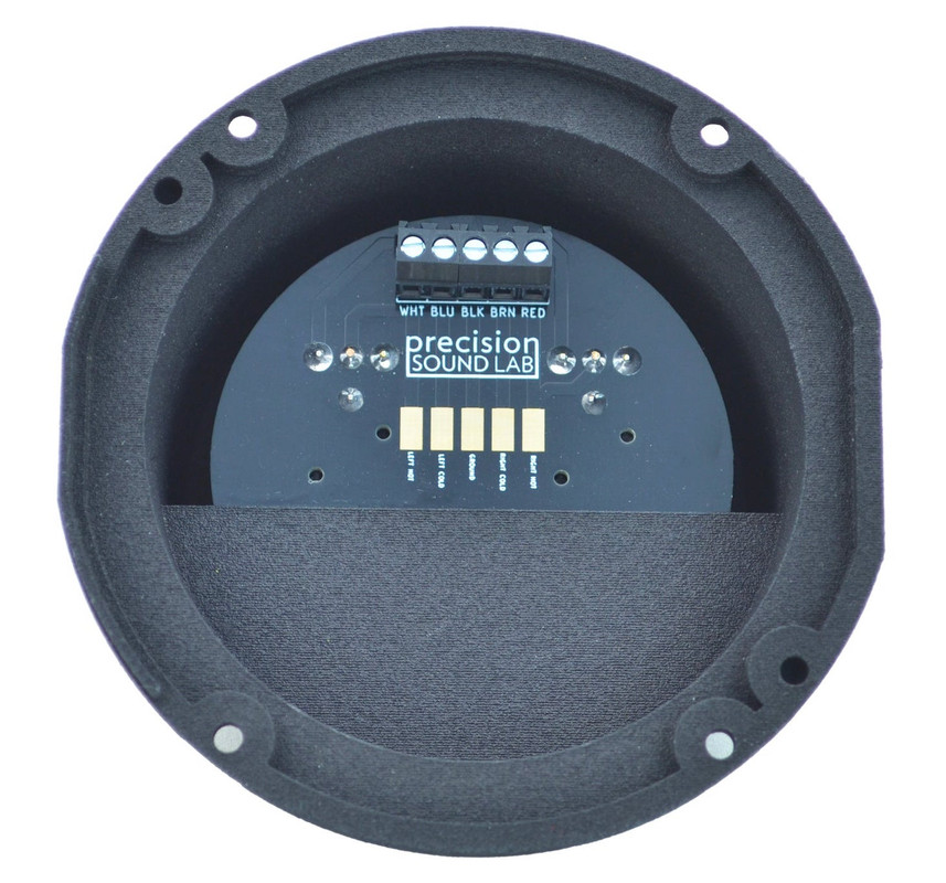
There are neatly available solder pads on the phono output PCB within the Technics, so the following is my thinking:
  1. L+ (white) goes to pin 2 of the left XLR;
  2. L- (blue) goes to pin 3 of the left XLR;
  3. R+ (red) goes to pin 2 of the right XLR;
  4. R- (brown) goes to pin 3 of the right XLR.
Note that the Technics uses brown instead of green for R- for whatever reasons.

So what are the problems, you may ask?

Questions
  1. Can you do a sanity check on my thinking above?
  2. More importantly, what about the ground wire?

    I will be using standard balanced interconnects, and no way to modify the cable itself (nor would I want to). I've seen balanced output cables that have a separate ground wire, as well as ones that do not.

    For example, the PrecisionSoundLab kit does not have any provision for a separate ground wire.

    Should I just connect the ground wire (black pad) to (1) pin 1 of either XLR, (2) pin 1 on both XLRs, (3) neither?

    Ideally, I would want to do away with a separate ground wire.
Thanks! :)
 
Interesting topic.. I am not the best one to reply to your question, however also interested in the outcome..
I would add some lateral thinking since you did not mention which phonostage/how much gain you are having and needing..
How about a single ended connection from tt to sut and balanced from sut to a mm fully balanced throughout phono stage..
 
which phonostage/how much gain you are having and needing

I did but it is burried in the text. It is the Elac PPA-2 (which is why I reached out to them initially). It works suberbly with a SE connection, but I have it balanced out to the headphone amplifier, so I thought I'd retain a balanced chain end-to-end.

Additionally, I have done away with SUTs for the foreseable future. In my system(s), active headamps (pre-preamps) work better.
 
Does this not add to what in most cases is already considerable scope for ground loop problems? Just curious.

I have done away with SUTs for the foreseable future. In my system(s), active headamps (pre-preamps) work better.

Here too - SUTs are a real gamble by comparison, and overall not worth the endless grief in finding one that you like the sound of musically, but does not pick up noise from everywhere.
 
Wire the turntable ground to pin 1. The Elac documentation is confusing and I think incorrect. A conventional balanced connection will be of screened twisted pair, the pair to pins 2 and 3, and the screen to 1.

FWIW a cartridge isn't balanced, it's floating. Not quite the same thing. AFAICT you get no advantage at all from a balanced input and in practice one side or the other will be doing most of the work. I don't understand the fashion for it at the moment.
 
Wire the turntable ground to pin 1.

Meaning the tonearm ground, right? Apologies for being so thick - the Elac has separate grounds for tonearm and turntable chassis FWIW.

I don't understand the fashion for it at the moment.

Granted, I don't expect a night-and-day difference. Just wanted to check for myself having the opportunity to do so.
 
I would expect that if the arm and TT chassis grounds aren't connected inside the TT then the TT organises a separate ground. At which point connecting them would might be bad. My interpretation of the Elac manual is that the separate ground connection by the phonos is not intended for use when using the XLR inputs.

So I would wire the arm ground from inside the TT to pin 1 on the XLR sockets and go from there. If you get buzzes then investigate further.

Nice job on the output plate mod, BTW.
 
So I would wire the arm ground from inside the TT to pin 1 on the XLR sockets and go from there. If you get buzzes then investigate further.

Sure - I will connect to left XLR only and see where that takes me. I suspect connecting to both XLRs might bring forth unwanted results.

Nice job on the output plate mod, BTW.

Thanks - I have a CAD file here that I drew up to serve as a drilling template. I will share all that as a package once I am done, including wiring diagrams and a STL file for the screening can - I suspect that the screening can will not be able to cover both XLRs. So one could either bend one from sheet metal, or, I am hoping, 3D print one and line it with copper foil to serve the same purpose. :)
 
I will connect to left XLR only and see where that takes me. I suspect connecting to both XLRs might bring forth unwanted results.
And this would appear to be the catch-22 with using 2 x XLR3 mic cables from tonearm into balanced inputs on phono stages.

Specifically, one unshielded cable would seem to defeat the purpose of using balanced to avoid noise induction along the line in the first place. IOW, one is creating a scenario where balanced differential mode is required to offset a potential problem that is the result of going balanced in the first place.

As the tonearm earth reference will be the phono stage, perhaps it would be prudent to leave the shield pins disconnected at both XLR sockets within the turntable and simply rely upon the Faraday effect of the phono stage being extended back along the two cable shields (i.e. via the shields being connected at the phono stage end only), and connect the standard dedicated earth lead from TT to phono stage.

Anyway, you'll soon find out how things go, might not be a problem in need of a solution in the first place.

P.S. Another thing to consider is that should you be using a MM or IM type cartridge with one channel -ve connected to cartridge shield then that channel isn't technically floating, as that channel -ve won't be at the same potential as +ve. Some MM/IM have a obvious metal tag connecting with one of the ground tabs out back. Others may require use of a multimeter set to continuity/impedance mode with one probe touching cartridge shield and the other on each negative pin in turn. Most MM cartridge makers connect Rch -ve to can. Doesn't apply to MC cartridges.
 
Last edited:
Well, I am resigned with the fact that it may bring no advantages whatsoever, but it is a relatively easy thing to try, and fully reversible as I am not destroying the original back plate.

Having said that, I will only be usin low output MCs - so not worried about the -ve connected to can. The idea is for both options (RCA and XLR) to be readily available.

There might not have been an issue with this at all for me, just use pins 2 and 3 on each XLR and connect the dedicated ground lead but I saw this and it threw me:

https://precisionsoundlab.com/products/xlr-sockets-mod-for-technics-sl-1200g-gae

As can be seen, there is a provision to connect / solder the tonearm lead internally, but there is no outside connection for a ground lead. Now, on the instructions for their RCA output box, they advise connecting ground to L- which does essentially the same thing you mentioned as some MM makers (and defeating the "floating" part).

There are no details as to how is ground connected for their XLR box.
 
Hopefully my prior post didn't come across as dismissive of your project. In fact, as a 'purist', I am impressed by the lengths you've gone to in order to preserve the original parts in order to make this 100% reversible. And a fine job installing those sockets too.

Judging by the graphics and PCB tracks that are visible on bottom of the Precision Sound Lab XLR sockets mod, it appears that they've split the existing ground out to both XLR socket pins 1 (i.e. the LH solder points of the three either side of the logo). It does appear that they've reversed their hots and colds though, presumably with their 'cold' (should be 'hot') connecting to the RH solder points on the other side of the PCB.

XLRG2-1024x1024-2x.jpg
 
Hopefully my prior post didn't come across as dismissive of your project.

Oh, no worries at all - it is but an exploration of possibilities.

If nothing else comes out of this topic, maybe someone in the future comes across this and decides not to bother with it at all.

But at the time being, I have (1) a floating cartridge, (2) balanced input/balanced output phono, (3) balanced headphone amp, (4) balanced headphones.

So let's see where that might take us.
 
When you break it down like that, even my OCD is being triggered.

In the meantime, does that bloke in the video look like a young Geddy Lee of Rush fame, or no?
 
It's done.

Connected according to discussions above. Grounding post connected to pin 1 of both XLRs, external grounding cable to phono stage not used. Most important, it works. No hum, no buzz, no issues whatsoever.

After a few records, it sounds, for the lack of a more descriptive term, better. Noise floor has been pushed further down, even if by a smaller margin. It is easy for me to compare because I can connect both RCA and XLR to the different inputs of the phono stage and just switch using the front panel buttons. I will give it a few more days as I am waiting for a balanced interconnect which is identical to my RCA one so I can say for sure it is an even proving ground.

But I don't see myself, in this system constellation, going back to an unbalanced tonearm connection.

And it looks not too shabby if I may say so myself. Almost as if Technics themselves intended to sometime put XLRs here:

viber-image-2023-02-07-15-46-57-182.jpg


I took a few pictures while doing the work. If there is interest, I can post them along with the process.
 
Glad to hear that all is working as intended.

From the POV of comparing optimized apples with optimized apples, are you installing a dedicated ground wire when trying out the RCA to RCA connections, compared to XLR to XLR only (and then removing same when switching back to XLR)?

BTW, it appears that you might have a bit too much negative camber on the back wheels there.
 
Last edited:
are you installing a dedicated ground wire when tying out the RCA to RCA connections

I did just by disconnecting from the phono. I had the rack angled to be able to access both front and back. :)

BTW, it appears that you might have a bit too much negative camber on the back wheels there.

Yeah, I saw the photo and then triple checked. All is good - probably iphone photo processing adding weird lens distortion.
 
Not meaning to spit in anybodies beer, but I don't see any technical benefit of balanced input for phono pre-amps, and some minor disadvantages - in some limits it can cost you 3dB in SNR, but less in most realistic cases.
 
It feels 'right' to use screened twisted pair with the screen being the screen, rather than coax with the screen acting as screen since attached to signal 0v somewhere down chain. And if you use XLR then you don't need a separate ground wire with a terminal post and all the mess that entails.

But I see no point in an actually balanced input for phono.
 
Not meaning to spit in anybodies beer

Oh no worries here at all. I understand that my circumstances may be very specific, and not everyone will have a configuration similar to mine. But I've always been intrigued by these claims of balanced operation, and now that the opportunity to test the claims has presented itself, how could I refuse the call of "science"! :)

but less in most realistic cases.

Agreed - and at some point I aim to record the output of both the RCA and XLR inputs with the phono and compare them - but at this point still letting my brain "bed in" around this addition.

But I see no point in an actually balanced input for phono.

And you ultimately may be right. I have no other way currently to confirm my bias for balanced input than my subjective impressions, but maybe able to show some empirical approaches soon.


advertisement


Back
Top