advertisement


Avondale NCC300 amp project ..

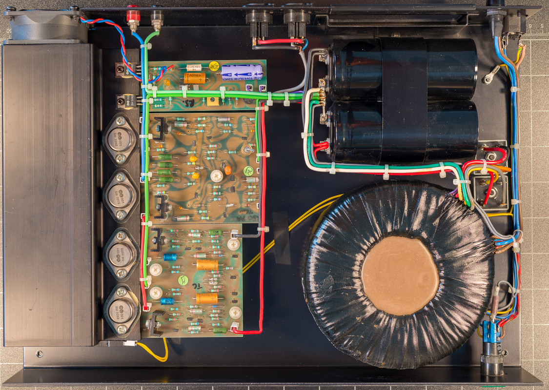
Oooh, she's a beast, Graham! What are the specs on those traffos, and how are you powering the front ends?

The trans are what Les supplied, AST jobbys. 530va 2 x 42-0-42 = 60vdc rails to the outputs (both secondary paralleled) and the front end from this main board supply via the links to the regs. With luck I'll be listening to it later today....
 
Those ASTs are a perfect match for the the Holden & Fisher in the 135. Do they have the extra windings for the fan circuit?

I forget how high a voltage the NCC220s can take, but it could be interesting to take them up a notch with that AST.
 
Those ASTs are a perfect match for the the Holden & Fisher in the 135. Do they have the extra windings for the fan circuit?

I forget how high a voltage the NCC220s can take, but it could be interesting to take them up a notch with that AST.

Hi Flash,

Yes, theres additional winding for the fan....I believe. I don't think the 220s will take 60v or were designed to do so..the 300 has the additional devises which allows the extra volts..

Graham
 
OK ..Here's my progress this morning

38958246010_875fb1e36a_h_d.jpg


38958247160_be165fbd93_h_d.jpg


38958246290_89231d6f5b_b_d.jpg


39873505755_5de94f98b4_h_d.jpg


Yes its powered up on the bench, no flash, no bang, no smoke...result.

I'll do some final setting up, I note the regs were set up at 55v on the bench without the outputs in circuit but now in anger they are at 50v +- 2v. Nothings getting warm 'as yet' So Ive set all the regs to 50v and rock steady.

Fabulous... I wish I could 'do' wiring so neat...
 
LOL, I was just looking at that Les and was going to drop the 2n5551s back in.

I have one amp board set to 2.2v and the output 15003 & 4's are warm, at 2.5v their getting nice and warm...Domesticity now in place, so play stops till tomorrow. :(
 
Last edited:
When available I'd like to try this NCC300 and integrate a pair with my NCC220s as they are now flying after more than a month of burn-in, due probably to wrong choice of caps bypass. (wimas...)
 
Up early and back at it ....final checks with the sig gen. and scope all good (just on one channel to start with) ....offset 1.5mv bias 2.2v. Hooked it up to a pre and JR149's the other end...

very bloody good indeed..more to report later on, I've never heard these little speakers sound this good. I'll let it play for an hour or two and re-test, then on to the other channel.

The 2k7 I changed to 3k3 and the 2k2 I dropped to 1k2 but this is too much...as with these two changes the bias is off to +3v which translates into very hot output devices in short time. Other changes were tried as I had a little difficulty in gaining more than 1.0v bias at first. Which it turned out to be my error by installing the DB237 incorrectly. (advised by Les see previous post.)

So just change the 2k7 to 3k3 and with this there is plenty of available bias if wanted..2.5v is too much IMO as the spreader gets to warm after only a 5-10mins.

The next thing of note is the silence, (Flash is right when he said darkness) even at switch on the faintest pops hardly detectable through the speakers (no speaker protection at this stage) and then a total absence of noise from the tweeter with ones ear up against it. At first I thought the amp wan'nt powered up...but it was and a gentle twist of the vol knob.. provided the proof it was working.
 
Graham, to say I'm pleased for you is an understatement - I'm like a dog with two tails
hearing the news. Although the NCC200/220 have very little residual noise, I hoped the
current mirror configuration plus fully complimentary output strategy of the 300s might
reap rewards - it seems very much like it has. Don't you love it when a plan comes
together.?

Congrats on a job well done Graham........
 
A quick helper for those building at a later date...

There are no test points for the bias setting so leave one leg clear on both 15R resistors off the PCB so when it comes to setting bias voltage its easy to attach the probes.

40803404261_ac6f906bb2_h_d.jpg


Be extra careful when soldering the legs, MJE15030, MJE15031 ZTX753 & 653...its a bit tight.

40803417191_df0c517ba8_h_d.jpg
 
Last edited:
Graham,

You've got your transistors flying high above the PCB. What's your reasoning?

(I also discovered the trick of popping up the resistor legs to use for test points. Along with that, DMM leads with small spring-loaded hooks came in invaluable on this build.)

Flash
 
Graham,

You've got your transistors flying high above the PCB. What's your reasoning?

(I also discovered the trick of popping up the resistor legs to use for test points. Along with that, DMM leads with small spring-loaded hooks came in invaluable on this build.)

Flash

Flash,

I leave the 753 635 just a bit high to get some cooling .....I tend to leave a bit of space 'just in case' = just in case I need to pull them at a later date, its much easier with a bit of leg to work with. Ive never found that being tight against the board improves anything, or a detriment. But always willing to learn..

Graham
 
Graham,

I'd noticed that Naim gradually brought the trannies closer to the board over the years. For no particular reason, I'm in the middle ground with enough leg to accommodate a hemostat during soldering.

Flash


advertisement


Back
Top