advertisement


Avondale NCC300 amp project ..

Thanks S-man. I understand that the resistor draws more current from the regs but I'm lost after that. Do I need to set the regs at 39 volts beforehand. I take it I'd measure the regulated voltage before and after connecting the resistor. Do I do both regs together or one at a time and does this have any effect on the components in the bias chain? I take it the output stage would be disconnected from its psu.

I have a scope but wouldn't have a clue how to put a square wave load across the rails. I envisage more smoke rising from my amplifier if I tried that :eek: I think it's time I learnt how to use thing properly but I'm afraid by the time I've done that I'll be finished with all this.

Don't be under any misconceptions. I'm no racehorse and I can't believe the speed that some of these guys can build things. I've been trying to get these amps built for well over twelve months now and every time I try to move forward I seem to go backward. I also feel like I've reached the limit of my abilities :(
 
I think you're underestimating yourself a fair bit here..
Your build quality, mechanical structure as well as design is outstanding.
Ok, sometimes there's issues or drawbacks..but still I think you are 80% if not rather 90% through.
Maybe take a step back for a week, let it sink..and get on to it with a fresh approach.
Or perhaps stick your head in together with someone in the forum who's not too far from you ?

That amp really looks almost finished to me, don't give up now ! :)
 
Thanks S-man. I understand that the resistor draws more current from the regs but I'm lost after that. Do I need to set the regs at 39 volts beforehand. I take it I'd measure the regulated voltage before and after connecting the resistor. Do I do both regs together or one at a time and does this have any effect on the components in the bias chain? I take it the output stage would be disconnected from its psu.

One reg at a time. The bias chain will not be affected.

The 39V was just as an example because 39V/3K9 = 10mA. If your rails are 44V then you would get 44V/3K9 = 11mA.

The method you suggest of checking the voltage with and without the extra current draw is correct. However it has just occured to me that it may be tricky to measure a deviation of mV when the dc voltage is around 40V.


The other way to check the operation of a regulator is to check line regulation (the above method is an attempt to check load regulation). To check line reg you need to vary the input/supply voltage to the reg and ensure the output voltage is (almost) constant. The easiest way to do this is with a variac to vary the supply voltage.


The good thing is that if you can adjust the output voltage of the regs then it is highly likely that the regs are working properly (in much the way as if you can adjust the bias current and have a few mV of dc offset on a power amp output, then it is usually working). So maybe it best to assume all is OK and proceed with your amp build.

If you are anywhere near Leeds, I would be happy to check this stuff out for you.
 
Thanks, I understand that. I have the regs set at 50 volts so they’d be delivering just shy of 13mA into 3k9. I can vary the output of both regs so I’ll check the range of each later and if that’s good I’ll assume they’re ok and press on.

I like the idea of varying the dc supply to each reg and I might be able to get hold of a bench supply.

Thanks for the offer to check it over for me. I’ll bear that in mind but I feel confident I’ll have them singing tonight. They were actually singing very nicely before I smoked the right hand channel:(

And thank you torstoi for those words of encouragement :)
 
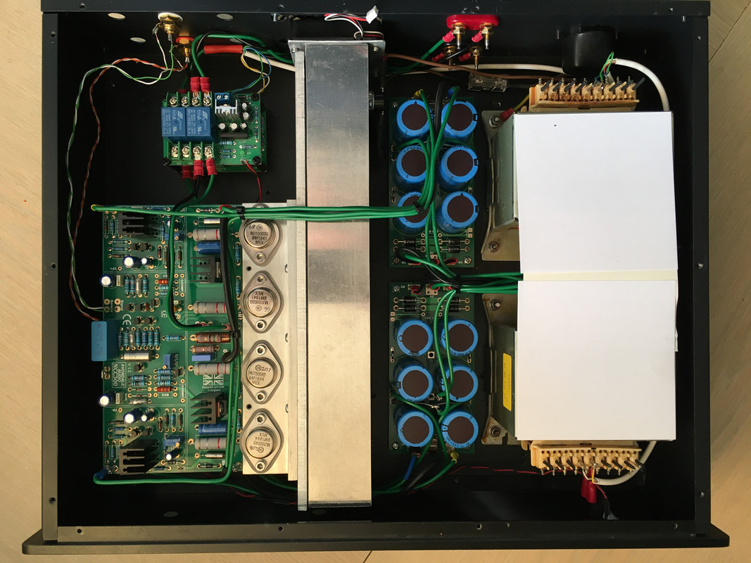
I thought I'd post some pics of my 300 build. I was laid off at Easter and as I was going to get the enclosures made at work that idea went out of the window. As funds are tight I needed to get creative so I decided to build both amps in one box. I prefer monos but needs must and I just happened to have an old defunct Mac G5 gathering dust so it was duly gutted and cut down.

The transformers sit on a base plate on the bottom of the enclosure.


For each NCC300 I understand 2 transformers - a la Voyager.
So for 2 NCC300, I understand 4 transformers.

I don't understand why you have 5 transformers.

Can you help me, please?

BugBear
 
Hello BugBear. If I was building monos there would be three in each amp. The third one is for the loudspeaker protection board. Because I’m building monos in one box I’ve used one transformer with two secondary windings for the ls protection boards, one winding for each board.
 
Hello BugBear. If I was building monos there would be three in each amp. The third one is for the loudspeaker protection board. Because I’m building monos in one box I’ve used one transformer with two secondary windings for the ls protection boards, one winding for each board.
I didn't realise the LS board needed its own PSU. Thank you.

BugBear
 
I'm using a pair of Les's LS protection boards which also include fan control. I'm assuming they're a drop in replacement for some of the Naim amps.
 
Must be my slowest/longest build ever, but my NCC300 is currently up and running on the bench. It's more or less finished, just need to add the power supply for the fan. Seems to run surprisingly cool without the fan though.
 
David glad to here your amps are up and running and look forward to hearing your views on them
IMHO As long as you have the NCC300 bolted to a decent heat sink you don't need a fan.
Mine run at 120ma and the heat sinks are only hand warm
Alan
 
Great stuff S-man. I always thought I'd be the last one to finish ;)

I have 2.3 volts across the bias test points and mine run cool though they do have quite large heatsinks. I intend to increase the bias at some stage but I'm just happy to enjoy them for the moment.
 
I am running with:
Iq per output transistor is ~50mA (11mV across 0.22R)
B+/- = 39V
A+/- = 58V. Regs set to +/-41V

Output stage dissipation is ~8W per channel

It all fits in a 100mm H, 410 W, 340D chassis with no external heatsinks, so it's intended to be forced air cooled.

I will try to post some pics later (seem to be booked in to a 3D immersive Van Gogh exhibition in York today :eek:)
 
I still like to set the Bias both ways measuring the output end + rail current draw in mA and measuring the BIAS voltage between the output's of the 15R resistors RS1 & RS2
Graham lifted the leg on his resistor to facilitate this, I inserted a test pin on the inner vacant hole of the CComp
Its been a while since I did it but I have noted down the following readings
2.2VDC gave me 110ma
2.23V gave me 120ma
2.3V gave me 220ma
I settled on 120mA / 2.23VDC
Alan
 
S-man, I’m assuming it doesn’t matter which .22 ohm resistor you measure across?

Not really, however the readings from the parallel ones should ideally be close to each other - then you know that you have a good chance of current sharing in the parallel output transistors.
Might be a good idea to measure the actual values of the 0.22R resistors first, so that when use I=V/R you get a more accurate result for the current.
 
Thank you S-man. I read your post wrong but I understand now I’ve had time to go over it again.

Alan, I used to set the bias on my ncc200s by measuring the current draw to the positive rail. I think maybe I should do this with my ncc300 as well. After my magic smoke moment I’ve put test pins on the board the same as you have :oops:
 
A couple of pics:

IMG-1005.jpg


IMG-1011.jpg


All tests so far look good. Square wave into 2u2 is as expected.
Output into 10R is 24VRMS just before onset of visible clipping = 57W
(I estimate it would just about reach 70W into 8R at the current mains voltage, so let's call it a 60W amp)

In has been sat at 1/3rd power i.e. 20W into 10R for about 50 minutes. 1 channel driven.
The fan is not running and I'm waiting to check that the 55C thermal trip works (it certainly did in isolation). However it's going to take forever at this rate! The TO3 cases are only at about 45C.
I think I'm going to have to drive both channels or drop the load resistance if I want to fry eggs.

I will cook the "lower" channel for a while and then consider the soak test done.
 
I have hit a bit of a snag :(

With the lid on and the fan running, the quiescent current in the lower board climbs to about 75mA. I believe this is caused by the restricted airflow around the driver transistors, which are not included in the thermal feedback loop.
Ironically Iq is more stable without the fan cooling - basically the Vbe multiplier warms up a bit more in this situation and compensates/reduces the Iq.

Conclusion: the combination of the 2 level approach and fan cooling is not ideal for these boards (and is not how they were designed to be used!).

This could be fixed by thermally coupling the driver transistors to the main heatsink, or adding some airflow for the driver heatsinks on the lower board. In my situation, just removing the lid improves the situation. Overall it's workable and even in the worst case I don't think I will get thermal runaway.

It will cause my speakers to emit noise tomorrow :)
 
That's a bugger! Could you put another fan in the case itself so that air flows over the output devices?
 
Hi David,
Consider running Q6 from the upper board, under the upper board and Q6 on the lower board to a similar point on the output transistor heat sinks to stabilise the BIAS between the 2 boards
Alan


advertisement


Back
Top