advertisement


Audio Innovations Valve amps

Hi all,

I recently purchased a Series 300 Mk1 and am very happy with it. Can anyone give me guidance on replacement valves/brands to improve the sound? Also, can the MC stage handle low output MC's, I would quite like to get a Dynavector 17D3.

Thanks for any help

Hi MidrangeAddict,


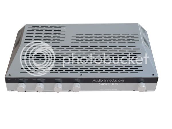
I also got a Series 300 AI amp but I don't it is MK1 .

Colour is Black. I checked inside have some parts have been changed.

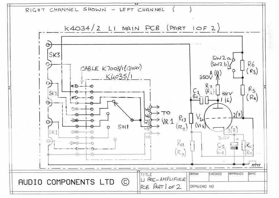
e.g. ECL86, ECC82, ECC803, 12AU7 I think someone put wrong tube.

So, do you have any idea to MK1 or MK2.

I can post some pictures.

Thanks..


AIUser
 
I had an Audio Innovations 300 MK 1, and it had a plain black steel case with a sloping front with cut out slots in it.

As I remember it had "Audio Innovations Series 300 Mk1" written on it as a clue to which model it was. I've had a quick look around and I still have some photos of the inside I could send you if you want and I think I might have a circuit diagram somewhere as well.
 
Why would it have 'Mk.1' on it ? That implies that the company already had plans for a Mk2 and no one would buy the older model !!!
 
I had an Audio Innovations 300 MK 1, and it had a plain black steel case with a sloping front with cut out slots in it.

As I remember it had "Audio Innovations Series 300 Mk1" written on it as a clue to which model it was. I've had a quick look around and I still have some photos of the inside I could send you if you want and I think I might have a circuit diagram somewhere as well.

Many thanks for your help..
Please send to me.

Good sound Tubes ECL86 http://img256.imageshack.us/img256/4893/bzmrz2b2kkgrhgohdeejlll.jpg


Moko please see my AI S300
http://img216.imageshack.us/img216/4290/audioinnovationsseries3.jpg
Does anyone know that is MK1 or MK2 ????


There is another AI S300 photo I search from internet---- http://img215.imageshack.us/img215/5861/audioinnovations300.jpg ----


Aiuser
 
the gain is swithced simply by a passive resistor cutting network, I think on the input of the stage.

its not via feedback at all. its been ages but I owned one and know them pretty much backwards, most of them.

l1 and 2 are the same circuit, l2 has a regulated shunt valve psu that you can turn into an l1 simply by removing the regulator tubes selectively, can't again recall which as its been SOOOO long since I pulled valve stuff apart.

L1 schematic showing switch to adjust gain

Page2-1.jpg
 
The first Series 300's were supplied in the case Moko's has. This was a very basic design with a sloping front and large rectangular ventilation slots. Despite the low price of £299 (the cheapest new valve amp you could buy in 1986) and fine sound, it took a fairly committed enthusiast to buy and own one. Fairly soon afterwards AI commissioned Rod Keith (now of Stands Unique) to design a more appealing case which would allow the existing innards to be fitted. He came up with a softer and more attractive case design which was available in cream/grey and later in black.

Series300Mk1image.jpg


the internals were identical with transformers from Hinchley in Devizes.

Later in around 1990 the 300 Mk2 was launched with some circuit modifications and was built into the casework with 4 corner pillars that was also used for the 200 series, L2, P2 and 400 integrated.
Mk2image.jpg


Hinchley had stopped making audio transformers by this time so transformers came from SP Wound components in Christchurch, Dorset.
 
That only shows the power amplifier part of the Mk2 schematic. I do have the full schematics of both the Mk1 and Mk2 should anyone need them.
 
Hi Pure Sound,

Please send to me.. Thank a lot .
I have question for the S300 amp. I found the amp. hum on right only .
Do you know why ?


Aiuser
 
That's strange I had an Musical Fidelity A100 then sold it to buy my Audio Innovations Series 300 Mk1...we are all on the same journey.

I really liked the A100 but god did the thing get hot! You just felt at sometime it was just going to melt itself or catch fire...probably both. But in saying that it sounded great.

http://img33.imageshack.us/img33/716/img0939c.jpg
 
The HT supply in the S1000/III was around 370v which included around 27v of cathode bias iirc. They weren't being run at maximum dissipation. The valve failure issues usually occurred when Chinese made EL34's were used. The Sovtek (Russian) EL34's were generally more reliable & robust.

The amplifiers 'could' be converted to fixed bias, but it would be quite involved to do it to a pair. If you have some of these amplifiers or are considering whether to buy some, I'd recommend you use them as is but with Sovtek or EH EL34's although some people do use the 'tough as old boots' Russian 5881's in them too.

Pure Sound
I have finally changed my AI 1000 mk III to active Bias,running the EL's 34 with 39 mA of bias. I had to duplicate the coupling capacitors to the EL's. For safety i added a fuse in the B+ to the output transformer (315 mA slow blow). Well i get a new sound, more clean and detailed and more control (this could be the silver/gold oil's capacitors i replaced for the old ones). Anyhow i added more capacitance to the output. Do you think i should reduce the feedback by changing the values of the voltage divider on the V1 cathode? As i could i might suffering of the so called "new component psico acoustics", what are the implications of the increase of capacitance in these monoblocks, oscillation?.
Best regards
 
The fuse is probably a good idea. 39mA seems a little low, the original standing current would have been nearer to 60mA per EL34. Better coupling capacitors may have helped.
Where exactly have you increased the capacitance 'on the output' ? Do you mean you've added capacitance to the power supply? I'd live with the changes you have made for a while before experimenting with the nfb.
 
I will try and increase the bias current to see what happens (are they now running at 50% of max dissipation rating?). I've added 2 more coupling capacitors (0.47 uF) and 2 more grid leak resistors (220k). So EL34's have their own interstage capacitor and independent bias regulation (i can send you, by pm, the schematics of what i have done). Active bias is provided by a module that is powered by mains AC (in my case power on switch) and claims to control cathode bias(output) through the grid leak resistor (input). As a more or less complex circuit was added to the equation, i wondered and had an answer from the builder of the modules: "The corner regulation frequency of the auto bias module is at 0.01 Hz, however at around 4 Hz there still can be enough amplification in the auto bias module. Together with the coupling capacitors inside the amp and the negative feedback in the amp, this can cause osillation around 1 Hz." The idea was to reduce NFB and not abolish it, but you are right, to many changes in row are a mess.
Regards


advertisement


Back
Top