advertisement


Arcam and the TDA1541

The bit decoupling caps i had in place (originals plus piggy-backed 0.22MKT and 1uF tants on MSB + adjacent) were removed and replaced with the Panasonic ones above. WOW you were right Mike, what a difference. :) I finally have some mid-range detail and the tonal balance is better along with the correction of "false treble" for want of a better description. Don't know if it was the 1uF tants or the combination (with the original ceramic chips) but the difference is quite something to behold. Some time after doing this mod I noticed the player had developed a hum of circa 2mV p-p, 100 Hz on the outputs. Eventually traced it to the 0V return of the -15V supply which is also shared by the bit decoupling caps. A soldered joint had fractured which was modulating this earth plane along with the audio signal. Just shows how important quiet supplies are. Regarding Martin's comments above about using a lower value resistor between the reg and the cap/supply pin. Measured the raw -25Vdc feeding the -15V reg and this has 1.5Vp-p saw-tooth on it and consequently passes 3mVp-p sawtooth through to the output side. I am going to increase the 220uf on the raw DC to 470uF as this should reduce it to about 0.7Vp-p (about the same as the +15V supply) and then place a 100uF on the -15V line just before the resistor that feeds the TDA -15V supply pin.
Once this is done and "settled in" i will do some back-to-back listening against my un-modded player.
Thanks again,
AP
 
Thanks Mike, much appreciated. Did the mods last night and the 470uF on the raw -25V supply reduced the ripple to 0.7Vp-p with about 1-2mVp-p saw-tooth out of the -15 reg. Also added the 100uF close to the TDA on the incoming -15V supply line. Almost no ripple at the -15V pin on the TDA (less than 1mV). However I seemed to loose a little clarity so will run with it for a while and if necessary, remove the 100uF.
 
Do you have any small film or ceramic bypass caps near the supply pins of the TDA1541 or are you using just the electros for local decoupling?
 
Mike,
According to the schematic, all three have small chips of 47nF (assumed to be ceramics) adjacent to the supply pins as original fitment. None were removed during original re-cap.
I have some of the 220nF PPS bit decoupling caps spare. Any use here?
Cheers,
Andy P
 
There are advantages to either. Ceramics generally have better high frequency characteristics and films are generally more linear.

By all means give the PPS a try if you want to.
 
Nice update, AP
Lower ripple should help always; and LM337s do need/benefit from some decent capacitance on the output, it helps keep the output noise down - http://www.tnt-audio.com/clinica/regulators_noise2_e.html

- but doesn't mean there isn't something else going on, perhaps some artifact in terms of layout overall in an Alpha 5 that is getting in the way. Or maybe simply that 'quieter' simply sounds odd/less exciting after years of familiarity (BT,DT...)

Let your ear be the arbiter, you are living with the thing and want to enjoy it!
 
Hi Martin, I may be wrong but I think AP is modding a Philips CD160 although this thread is originally about the Arcam A5 (a player I'm much more familiar with as you know).

AP, I know I keep banging on about it but if you haven't given the SAA7220 its own reg yet I'd urge you to do it. A simple 7805 will do.
 
Nice update, AP
Lower ripple should help always; and LM337s do need/benefit from some decent capacitance on the output, it helps keep the output noise down - http://www.tnt-audio.com/clinica/regulators_noise2_e.html

- but doesn't mean there isn't something else going on, perhaps some artifact in terms of layout overall in an Alpha 5 that is getting in the way. Or maybe simply that 'quieter' simply sounds odd/less exciting after years of familiarity (BT,DT...)

Let your ear be the arbiter, you are living with the thing and want to enjoy it!

Martin,
Yes it is a Philips CD160, maybe I should have kept it to my thread on this but picked up on a factor on this thread. I was also thinking that it could be the change from something 'odd sounding' to being much better tonal balance that just requires some readjustment of the ears / brain myself.

Hi Martin, I may be wrong but I think AP is modding a Philips CD160 although this thread is originally about the Arcam A5 (a player I'm much more familiar with as you know).

AP, I know I keep banging on about it but if you haven't given the SAA7220 its own reg yet I'd urge you to do it. A simple 7805 will do.

Mike,
I will try this as a last resort as I wanted to keep it as close to standard as possible, although I have cap multipliers on the supplies to the output op-amps and an ALWSR on the +5V to the TDA so you could argue I have already crossed that bridge! I also remembered last night that there are no small decoupling caps on the op-amps so I have +/- 15V supplies (7815 / 7915) and cap multipliers which drop these down to about +/- 14V feeding the 47uF decoupling and then the op-amps but the base resistors are probably too large (12k IIRC) as I get about 3mV ripple (audio modulation) and ought to reduce the base resistor value, but this is much better than the 100R + 47uF that fed these op-amps that was causing about 100mV audio modulation on the supply. I think there could also be some room effects (12ft square floor, 7'-6" ceiling, firing diagonally across the room) that are now more obvious because of the change in tonal balance. Even with the dodgy earth mentioned above it just sounded so 'right' and after fixing that I put a 470uF on the raw -15V and then a 100uF on the output side, close to the TDA1541 and it is since doing that that I noticed a slight loss of detail. I will try removing the 100uF if this persists.

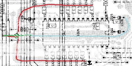
Any comments on the earth layout would be appreciated. Both ground connections (pins 5 and 14) on the TDA chip are connected to a trace under the TDA along with the decoupling caps for the +5V and -5V supplies. The -15V supply decouples to the bit decoupling earth plane and both of these are commoned where they connect back to the upper ground plane. Therefore the -5 and -15 (which has a 10uf tant connecting them that gave a small improvement in clarity) are locally earthed separately but remotely earthed together at the ground plane. Is this worth rearranging?
 
Mike,
I will try this as a last resort as I wanted to keep it as close to standard as possible, although I have cap multipliers on the supplies to the output op-amps and an ALWSR on the +5V to the TDA so you could argue I have already crossed that bridge! I also remembered last night that there are no small decoupling caps on the op-amps so I have +/- 15V supplies (7815 / 7915) and cap multipliers which drop these down to about +/- 14V feeding the 47uF decoupling and then the op-amps

Yeah, I think you crossed that bridge a while ago! Adding a dedicated reg for the SAA7220 in my experience is one of the most worthwhile mods you can do, it's really easy and costs hardly anything but if you don't fancy it that's fair enough.

If you're using fairly pedestrian opamps I wouldn't stress too much about local bypass caps but if you fit anything much faster then tight local high quality decoupling is advisable to ensure stability of the opamps.

Having good quality electrolytic decoupling caps for the opamps and TDA1541 (e.g Panasonic FC and Rubycon ZLH) definitely makes a difference.

I've plenty more suggestions too but it depends how far you want to go with it.;)
 
Mike,
Please don't be a tease ;). I am already suffering the comments / looks of the "Hi-Fi widow" so best not go there!
Think I will get some stripboard and a couple of 7805s and make a small circuit board so I can remove the ALWSR (fed by rectified / unregulated 11Vdc) and use that with the pair of 7805 regs for the SAA7220 and TDA1541. Lets face it I can't really get much better recommendations than Martin Clark and yourself (sorry if that sounds a bit ar5se-lick):eek:
Are the 7805 output side caps critical for stability?
AP
 
That's very flattering A.P.

Martin's understanding of electronics is vastly superior to mine and we're lucky to have the likes of him on this forum.

All I have to offer is bucket loads of first hand experience of tinkering with TDA1541 based CD players.

Many years ago when I still learning which end of a soldering iron was the hot end I bought an Arcam Alpha 5 CDP. With considerable help from Martin I modded the heck our of it and that's what got me hooked on the TDA1541. I've not stopped since then and I've honestly lost count of how many TDA1541 based CD players I've owned, repaired, serviced or modded but it must be 20+ .....and counting!

Regarding the 7805 output cap stability - The datasheet calls for at least 330nF on the input side and 100nF on the output side. As far as I've experienced the 7805 is generally stable unless there's too much distance between the reg and the caps on either side. On the input side go as big as you like and if the big electro is too far away add a small cap of at least 330nF close to the reg. On the output side, if the local decoupling cap at the power consuming device is too far away add at least 0.1uF near the regs output. The electro on the output side can be large but if it is big then you should add a reverse diode across the reg to allow the charge in the capacitor to discharge safely past the reg when the device is powered down.

But don't take my word for it, wait until Martin replies!!
 
Can't disagree with that at all Mike except maybe the flattery :)
The fixed voltage regs, and LM317s in and of themselves do not actually need an output cap for stability, but in-circuit performance is better with one, obviously. I don't like small-value, low-esr caps alone on the outputs of these (it's a good way to upset the reg*) - and in any case small-value, HF decoupling caps like those values belong at the load they serve - not ever at the regulator.

* http://www.acoustica.org.uk/t/3pin_reg_notes3.html
 
Last edited:
That's very flattering A.P.

Martin's understanding of electronics is vastly superior to mine and we're lucky to have the likes of him on this forum.

All I have to offer is bucket loads of first hand experience of tinkering with TDA1541 based CD players.
......
But don't take my word for it, wait until Martin replies!!

Mike,
Couldn't agree more.
Was trying to sort out a small psu over the weekend but a "heavy night" on Friday (too much whisky) left me feeling decidedly rough!
Anyway I connected a lm317 up wrongly three times, the third time after i had found the pin-outs from an old circuit diagram :confused:. Once I'd got the pin-outs sorted I ran it for about 3-4 hours into a dummy load and it seems to have survived (despite my best worst efforts). I am using 47R // 47R before a 1000uF cap (drops the incoming 11Vdc with 0.7V p-p saw-tooth to 60mV p-p rounded at about 8.5V with circa 100mA drawn by the regs) and feeding this to an lm317 and a 7805 (as that is what I had to hand) so that I can power the TDA and SAA7220 +5V supplies individually. I thought (from previous posts by such as Martin) that 4µ7 of about 2 ohm ESR would be OK on the regs outputs so that is what I used. Both have nice clean outputs with about 1mV of noise. Before I install this I wanted to know if it is permissible to use a ferrite between the reg output and cap/input pin of each device in order to avoid noise going back from especially the SAA7220 into the supply, or is this likely to cause issues with ringing?
Cheers,
AP
 
Hi AP,

I'm not familiar with the Philips CD160 but typically the 'better than average' TDA1541 based machines have a power supply arrangement something like this:

7815 and 7915 feeding opamps in analogue stage and also TDA1541 -15v supply.
7805 and 7905 daisy-chained off the above, to supply +5v and -5v to TDA1541

7805 and 7905 to supply digital section IC's.

I would then give the SAA7220 its own dedicated reg, taking the supply for this new reg from the same point as the 7805 in the digital section is fed from.
 
Last edited:
+2 to that.

if you want to split-out supplies further - 1. ensure the SAA7220 has its own reg; 2. ensure the TDA1541A has its own three regs.

Beyond that - 3. Realise that the TDA1541A +5v supply as a dynamic load 'sees' the 'complement' of the dac's output current i.e (in conjunction with the decoupling cap on this supply pin) addresses the +/-2mA max current draw per channel in opposite-sense to the dac's output. So ideally, would provide a fast, low-overshoot/critically-damped supply response on this pin in conjunction with the decoupling cap fitted.

There's a nice challenge ;)

NB there is a very elegant potential answer, that is likely hard to deliver - if your I/V opamps can do the necessary from only +5v supply also, then, powering them from the +5v supply feeding the TDA 1541 has the potential to entirely-cancel-out the signal current component!


(for myself, I use brute-force I-V via fast opamp with a discrete-parts class-A buffer inside the f/back loop so the opamp is unloaded and can so its job properly. Not a go-er only +5v supply)
 
I made a bit of a hash of the supply board as I got my current figures wrong. TDA +5 uses 45mA and the SAA7220 uses 180mA (I had allowed 40 and 60 respectively, not sure why) so I had to adjust the resistors feeding the local smoothing cap form 47//47 to 47//47//27. I now get 7.8Vdc (70mVp-p) feeding the regs from the 10.7Vdc in, and am using a bit of copper as a heatsink on the 7805 feeding the SAA7220 as that is dissipating about 0.6W. First impressions are that the mid is clearer and better defined but as a consequence there is a slight perceived loss of top-end, but I only got an hour last night so will give it time to settle in. No apparent 'nasties' on the supplies and the ferrites keep a lot of noise from going back into the supplies.
Martin,
I had a read through the stuff on your link, and the Werner Ogiers link from that which makes for interesting reading, especially with regards to the supplies' impedance which is what I assume "changes" the tonal balance / sound. I also need to "get my head around" what you have said above in point 3! On the LM317 feeding the TDA +5V supply, I used two yellow LEDs in series bypassed with 0.1uF polyester (as the LEDs have about 6 ohm impedance each, so that is 12 ohm instead of 680R to get the 5V output with 220R from 'out' to 'adj') and so though it was less critical to use 10-100uF there. Is there an ideal ground-plane arrangement for the TDA? Reason I ask is that the +5V and -5V share the same trace under the TDA chip, whereas the -15V and bit-decoupling share a separate earth plane, with both being common'ed back to the ground plane close by, see attached?
CD160%20TDA1541.jpg

I also have 10µF tant between -5 and -15 supplies
Cheers,
AP
 
Put about 20 hours on this now and there is a little more mid-range present but forgot to mention that whilst "poking around" I noticed a weird signal on one of the TDA1541 bit decoupling pins, a stepped signal (three steps down, followed by one step up) that was about 20mV total and 30µs duration. Traced this to a cracked track from pin 10 to the capacitor so removed the cap and replaced it as well as scraping the varnish off and bridging with solder. There now seems to be a more solid stereo image, but I still get some vagaries (centred vocals in headphones that are offset to the left on the speakers) which I can't put my finger on but I think may be due to room effects. Anyway the improvement is subtle but for the better so I will compare back to the unmodded machine as well as a micromega drive 3 feeding a bushmaster ii through headphones


advertisement


Back
Top