advertisement


Another Avondale Amp

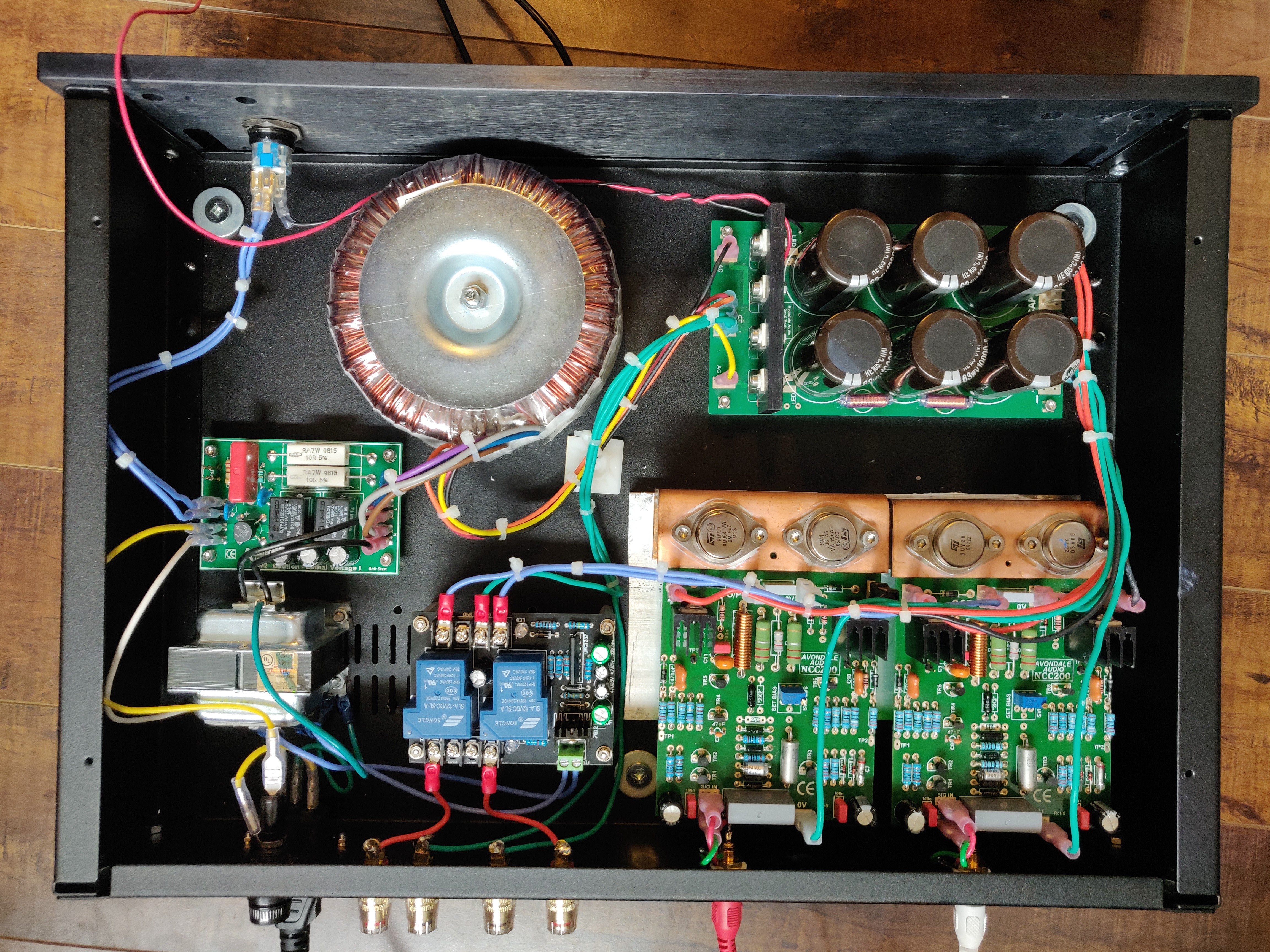
I just remembered than when I ordered those two boards, I also ordered an alternate with relays from Songle rather than Omron. That one was substantially larger, so I set it aside and decided to proceed with the two smaller units. (It also meant that I could get used to using just one style.)

I just pulled it out and hooked it up to my amp. When I switched it on, as soon as the SSM2 gave it power, one LED lit up. A few seconds later the other LED lit and the relays clicked.

Therefore, it would appear that those two other UPC1237 modules are both duds. :mad: I'm not sure if I can do anything to revive them, or whether I should just go ahead and buy another of the Songle units from that same supplier.

It also means I need to drill some new mounting holes. Any advice for how to do that without dismounting everything from inside, so I don't get metal shavings in nasty places? I should probably just bite the bullet and do it the right way.
 
This site contains affiliate links for which pink fish media may be compensated.
I've drilled the new holes and mounted the new speaker protection unit. However, it's still not working. Recall that when I tested it by hooking it up only to the power, it lit the first LED on switch on, then a few seconds it lit the second and clicked the relays.

Now that I have the speaker (+) inputs and outputs attached, the behavior of the unit is not quite the same. It still lights one LED when it's first turned on. However, it's 10-20 seconds before the second comes on, and it slowly flickers on rather than coming on suddenly brightly. I don't hear that obvious click of the relays.

As before, there is no sound. If I jumper over the unit, though, then there's definitely music coming from through both channels.

Again, I've got only connected a single speaker (-) input, because it appears to have a ground plane shared among all input and output speaker (-) connectors.

Note the other unit (which never lit at all) stated it could take 12-18VAC as a supply. This new one states 12-16VAC. My transformer is rated at 16VAC, but I've measured slightly north of 17VAC. I'm not sure if that's an issue. (I assume it would simply make the regulator work a bit harder.)

Also, my transformer is 10VA, which I'm assuming is enough to supply this little kit.

Again, here is the spec for the UPC1237 chip at the heart of this unit: http://pdf.datasheetcatalog.com/datasheet/nec/UPC1237.pdf

Does anyone have any wise thoughts? I'm almost considering skipping the speaker protection module entirely.
 
I was just reading that spec sheet for the uPC1237, and it indicated that the chip expects 25-60VAC. However, the kit(s) that I bought indicated they expected much less.
My transformer actually has three outputs: 6VAC, 16VAC, and 24VAC. Perhaps I should just switch to the 24VAC to see what it does. Is that a terrible idea?
 
This site contains affiliate links for which pink fish media may be compensated.
If it works without the speakers connected then it's something to do with the signal or the gnd connection from the amps. Can you check the gnd to the protection board continuity.

Pete
 
Well, I have more information.
  • The ground connection is definitely fine, and I've confirmed that it's a ground plane, so only one connection should be necessary.
  • If I disconnect both speaker (+) wires, then it boots up fine.
  • If I connect only one at a time, then it works fine.
  • If both are connected, then it doesn't let the signal through (although it did work for a while at some point).
I have another problem, though. As I was testing, the speaker output from one channel touched ground!!! :( There was a tiny puff of smoke from the region near the little diode by the signal output, and the amp fuse blew. I'm not sure if it's safe to power it up again, or whether I've blown a component. I can't see any discoloration on the diodes or resistors. What's the best way to proceed now?
 
A puff of smoke no matter how tiny = something broken!
Fuses rarely blow for no reason = something broken!

So I think something is broken.;)

An amp will usually cope with a momentary short to ground. If the output is near 0V, there is no reaosn for much current to flow.

However if the output was not near 0V then see post #39.

How to proceed:
Power each channel of the amp up one at a time from a current limited bench supply and check every the B-E voltage of every transistor in the amp.
 
Ouch!

You need to check all the transistors etc before powering it back up, and when you do remove the output transistors and check the voltage on the speaker output.

Sounds like some damage has been done to the drivers and outouts if you have got smoke from the Baxandall diode.

Pete
 
And I've just hit the limits of my ability! <sigh> I could start dismantling things, but I'm not sure where I would go from there. I may have to ship this back to Avondale for repair.
 
Dear Mike
My skill level and experience are way below yours, but how about removing the DC protection board?
I have used a single Velleman and x2 Minicaps (I know they don't suit your mains voltage but your unit looks similar) using twin earths through a 10K resistor one to each cap bank as suggested by Avondale
https://www.dropbox.com/s/np5jss2z7hzmb0y/VellemanHacker.JPG?dl=0
Not doing this may be the source of part of your problem at least. If not I'll just "get my coat"
For this particular amp, there's only the one CAP6, so that ground is truly ground. It's connected to both the speaker (-) posts, as well as the speaker protection (-) input (to bring its ground plane to the same potential).

My other amp does have two CAP6 modules, but again, the ground for each is connected to the same CT on the transformer, so it should be fine.

I'm going to send a message off to Les to see what he suggests.
 
I hope he can fit a repair in for you ...I spoke to him this afternoon and he's busy with work till the end of January!!!
 
I hope he can fit a repair in for you ...I spoke to him this afternoon and he's busy with work till the end of January!!!
Luckily, Les had a spare pair of used NCC200 boards, which he was kind enough to drop in the post for me. (I was kinda hoping he would have some QUDOS modules, as my friend would have been chuffed, but we weren't that lucky.)
 
Success!!! After receiving the replacement NCC200 boards from last week, I was able to get my friend's amp going. There were a few remaining issues that I had to manage:
  • One of the prior amp boards had small spade connectors, so I had to reterminate one set of leads with the larger connectors.
  • It turns out that when I shorted the one board's output to ground, I also damaged the soft start module. Fortunately I also had an Avondale SSM2 in my other under-construction amp, so I just swapped that board over.
  • I hadn't connected the switch's LED yet. I experimented a bit, and decided to use a 100K resistor for the desired brightness.
My friend is coming to visit this weekend, and is returning my upgraded NAP110 (with both Avondale NCC200's and 110 PS module). We'll see how it compares to this new amp. I fully expect the new one to win, as it has:
  • Bigger transformer (with higher voltage and more VA)
  • Avondale CAP6 rather than their smaller 110 upgrade PS
  • NCC200's with Les' latest tweaks
  • More space for separation of components
  • Soft start and speaker protection, although these don't apply to the sound quality
Thanks for all of your help with this. Next up is my own amp, but that has to wait until I get coordinate some replacement bits from Avondale. After that I might build myself an amp with the NCC300 modules. ;)
 
Last edited:
Here are the innards, prior to adding the LED resistor and more cable ties:

MarkInside.jpg
 
Nice...but might be better to move the speaker 0's (neg) to the other end of the cap 6 (clean ground) at present there on the dirty end of the PSU.

Years ago Les always recommended wiring the speaker 0V's to the rectifier end of the cap6 / minicap. I didn't know that advice had changed ?


advertisement


Back
Top