
You are using an out of date browser. It may not display this or other websites correctly.
You should upgrade or use an alternative browser.
You should upgrade or use an alternative browser.
Another Avondale Amp
- Thread starter Mike Hanson
- Start date
A pedant writes:Below was/is my preferred layout in one of my first on my NCC200's
Even with the Pesanti I would bolt the power amp boards to the case side heatsinks not just the base plate, remember heat rises
Heat does not rise. Hot air rises, if it can (lower density than cold air). Heat can be readily directed via conduction (e.g. copper/aluminium)
BugBear
337alant
Negatively Biased
This particular project is waiting in the wings while I build another amp for a friend who's visiting in a month. It's a bit different, as it has an Avondale SSM2, 330VA transformer, single CAP6, two NCC200s, and UPC1237 speaker protection module (with a separate transformer). For those who are interested, the layout is like this (front on the bottom):

http://avzine.com/images/AvondaleAmpProblemA.png
I started by hooking up the power input to the SSM2, then connected the switch and transformers to that. Finally, I connected the transformer to the CAP6. I confirmed that the voltage on the output of the CAP6 was ±50V. All good so far.
Then I did the rest of the wiring, and prepared the check the bias. That's where I've hit a wall. I have two DMMs, so I hooked up one to each of the NCC200s. I turned on the amp, and both meters are reading 0ma. Nothing! Nada!
I've confirmed that all of my connections between the CAP6 and NCC200s are good. I've double checked that I had the meters properly connected between the CAP6 (+) and amp (+). Everything looks good, but no current flows. Here's another shot with the wiring between the CAP6 and NCC200s, with the (+) connectors disconnected for my bias test:

http://avzine.com/images/AvondaleAmpProblemB.png
The one thing I didn't try was twisting on the trimmer pots, as I figured there must be at least a little current flowing, even at the lowest setting. Perhaps that's my next step.
BTW, between each test I connect a 240R (5W) to drain both sides of the CAP6, so that I don't zap anything inadvertently.
Before I blow something up, are there are words of wisdom for how I should proceed?
Mike
I set the trim pot to the mid position before fitting
Check the fuse on the Meter's
Check you have the meter red lead connected to the 10A socket not the standard socket for voltage etc.
alan
Mike Hanson
Trying to understand...
That's an interesting idea. I do plan to feed my switch's LED from one CAP6, but I could install an internal LED into the other one. However, I notice that my CAP6 modules have an LED socket only on one side, so the other side would stay charged.Have you considered fitting the LEDs and droppers to the CAP6s? With these fitted my CAP6s discharge in less than a minute once the juice is turned off. They're also a very useful indicator when the lid is off.

Last edited:
Mike Hanson
Trying to understand...
These came out of my Voyagers, so I'm assuming that the trim pots are already pretty close to where they need to be. I suppose a fresh set of boards could be more than "mA", so it might be smart to start on the 10A DMM socket.I set the trim pot to the mid position before fitting
Check the fuse on the Meter's
Check you have the meter red lead connected to the 10A socket not the standard socket for voltage etc.
Chops54
pfm Member
That's an interesting idea. I do plan to charge my switch's LED from one CAP6, but I could install an internal LED into the other one. However, I notice that my CAP6 modules have an LED socket only on one side, so the other side would stay charged.
My CAP6 boards have a LED on both rails. Maybe later boards only have one? MiniCaps are like this and I modified mine to take a LED on the other rail. I have some later CAP6 boards stashed away and I'll dig one out later and take a look. Only one LED seems a bit daft tbh.
Mike Hanson
Trying to understand...
There are definitely ones out there with an LED on one side. I assumed that the LED connection was for an external LED, to show that the amp was on. You're additional idea of using them to monitor the CAP6 for a latent charge is probably beyond the initial intention.My CAP6 boards have a LED on both rails. Maybe later boards only have one? MiniCaps are like this and I modified mine to take a LED on the other rail. I have some later CAP6 boards stashed away and I'll dig one out later and take a look. Only one LED seems a bit daft tbh.
337alant
Negatively Biased
Then I did the rest of the wiring, and prepared the check the bias. That's where I've hit a wall. I have two DMMs, so I hooked up one to each of the NCC200s. I turned on the amp, and both meters are reading 0ma. Nothing! Nada!
I've confirmed that all of my connections between the CAP6 and NCC200s are good. I've double checked that I had the meters properly connected between the CAP6 (+) and amp (+). Everything looks good, but no current flows. Here's another shot with the wiring between the CAP6 and NCC200s, with the (+) connectors disconnected for my bias test:
http://avzine.com/images/AvondaleAmpProblemB.png
The one thing I didn't try was twisting on the trimmer pots, as I figured there must be at least a little current flowing, even at the lowest setting. Perhaps that's my next step.
Mike
in the picture above it looks like you have both positives disconnected to each amp board but also at the Cap6 ? the +ve connectors should be connected at the Cap6 or you have no positive supply ?.
With the Cap 6 fully discharged on both phases, disconnect the red +ve lead to one amp only, connect the red probe from your meter into the end of that lead and the black lead onto the +ve terminal on the amp board, I always fit a female spade connector onto the board +ve so my probe can be plugged in securely as you don't want to be connecting and disconnecting once the power is switched on.
Now switch the power on and you should get a Ma reading, set it for 38ma stable over a period of 20mins
When you switch the amp off drain both sides of the cap6 before connecting up the meter to the other board
If you have 2 meters you can do them both at once and this saves time
Alan
Mike Hanson
Trying to understand...
Thanks, Alan, but the problem is definitely the missing resistors. I'm expecting delivery of those midweek, so I can proceed with the project.
FYI, when I test the bias, I use alligator clips to ensure they remain attached.
FYI, when I test the bias, I use alligator clips to ensure they remain attached.
337alant
Negatively Biased
A pedant writes:
Heat does not rise. Hot air rises, if it can (lower density than cold air). Heat can be readily directed via conduction (e.g. copper/aluminium)
BugBear
Each to their own I guess but it doesn't make any sense to me to buy a case with heat sink side panels and then bolt your power amps to the bottom plate via C channel ?
Alan
Mike Hanson
Trying to understand...
I'm not sure whether you're referring to BugBear or me. My case doesn't have heat-syncs on the side. It's a regular Pesante like this. Therefore, my only option is to add the extra aluminum sync.Each to their own I guess but it doesn't make any sense to me to buy a case with heat sink side panels and then bolt your power amps to the bottom plate via C channel ?
andrewsutton
pfm Member
You might find that the sides are better than the base for heat sinking as their vertical orientation improves heat transfer to air.
Drill the sides. Mark, drill and tap the heat sink. I use 3x m3 screws as their heads fit between my fins. You could use something a bit bigger, I guess.
Cheers Andy.
Drill the sides. Mark, drill and tap the heat sink. I use 3x m3 screws as their heads fit between my fins. You could use something a bit bigger, I guess.
Cheers Andy.
337alant
Negatively Biased
Mike sorry I have never seen that Pesante before all previous models had had aluminium side panel heat sinks like the galaxy and it was good enough for the NCC 200 amps https://modushop.biz/site/index.php?route=product/category&path=67I'm not sure whether you're referring to BugBear or me. My case doesn't have heat-syncs on the side. It's a regular Pesante like this. Therefore, my only option is to add the extra aluminum sync.
The case you have says steel case which isn't great as a heat sink, did you take the option for aluminium ?
The Ncc200 amps are very stable but still need a bit of heat sinking besides the C Channel they are mounted on.
As Andrew says the vertical heat sink veins is the best way to provide natural cooling
Alan
337alant
Negatively Biased
MikeThanks, Alan, but the problem is definitely the missing resistors. I'm expecting delivery of those midweek, so I can proceed with the project.
FYI, when I test the bias, I use alligator clips to ensure they remain attached.
Yes OK I see your missing 220 ohm resistors so you have no rail voltage to the FE
Alan
Mike Hanson
Trying to understand...
No, I'm pretty sure it's the steel panel.The case you have says steel case which isn't great as a heat sink, did you take the option for aluminium ?
I've got that big slab of aluminum (3/8" thick), which should help.The Ncc200 amps are very stable but still need a bit of heat sinking besides the C Channel they are mounted on.
For comparison, my Voyagers have QUDOS boards, and the case sleds for those are 1/8" aluminum, with the C channel bolted straight on. The heat doesn't seem to be an issue, so I'm hoping that the NCC200s in my stereo amps are fine with the mass of aluminum.
laverda
pfm Member
No, I'm pretty sure it's the steel panel.
I've got that big slab of aluminum (3/8" thick), which should help.
I have a used a Pensate case previously and found it a bit flimsy to be honest...the steel chassis did need further support. I used a slab of 3mm ali (as that was what I had) and the addition of two extra feet to hold it up.
Mike Hanson
Trying to understand...
Yeah, it's not the sturdiest of cases, but it seems to be "good enough". If I eventually build an NCC300 amp, I'll probably go for the Dissipante instead.
FYI, I received delivery of the 220 ohm resistors today, and attempted to solder them in. Unfortunately, I discovered that the solder pads were missing on one of the boards. (I'm not sure where that pair came from. At one point I thought they may have been chiily's, but we've ruled that out.) I may be able to work around it, but I don't want to send those potentially flaky boards to my friend. Instead, I swapped over the ones that I was planning to put into my own amp.
Next I adjusted the bias to a steady 36mA on each board. Looking good!
Finally, I hooked up an input and a single speaker on one channel. Frustratingly, there was no sound. I tried the other channel, and still nothing.
Then I had a hunch. I'm using a UPC1237 speaker protection module from ebay. If I jumper over it, I hear music!!!! I'm not sure whether I've hooked up that unit incorrectly, or whether it's defective.
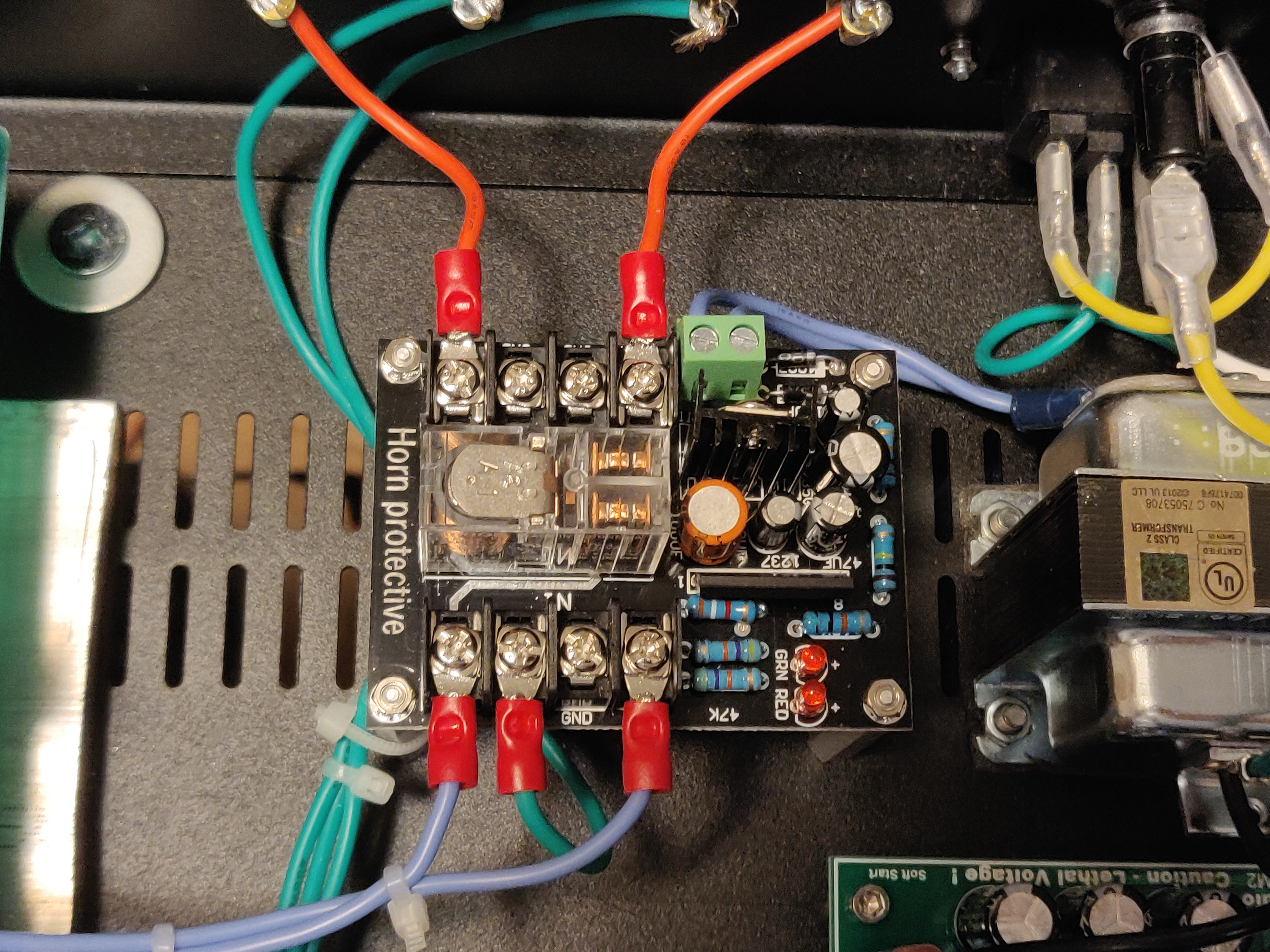
Here's the spec sheet for the 1237 chip: http://pdf.datasheetcatalog.com/datasheet/nec/UPC1237.pdf
Perhaps I need to attach all of those ground wires, and feed it only through the speaker protection module.
Does anyone have any experience with these things?
FYI, I received delivery of the 220 ohm resistors today, and attempted to solder them in. Unfortunately, I discovered that the solder pads were missing on one of the boards. (I'm not sure where that pair came from. At one point I thought they may have been chiily's, but we've ruled that out.) I may be able to work around it, but I don't want to send those potentially flaky boards to my friend. Instead, I swapped over the ones that I was planning to put into my own amp.
Next I adjusted the bias to a steady 36mA on each board. Looking good!
Finally, I hooked up an input and a single speaker on one channel. Frustratingly, there was no sound. I tried the other channel, and still nothing.
Then I had a hunch. I'm using a UPC1237 speaker protection module from ebay. If I jumper over it, I hear music!!!! I'm not sure whether I've hooked up that unit incorrectly, or whether it's defective.
- I'm feeding it with a 16VAC transformer (apparently it can take 12-18VAC).
- I've got positive input and output for both channels.
- I have a single negative input on one channel, just to connect to the unit's ground plane. Recall that Avondale recommends that the speaker negatives be connected to the transformer CT, and my Voyagers do that with a separate feed for the ground of the speaker protection. I've used the same approach with this.
Here's the spec sheet for the 1237 chip: http://pdf.datasheetcatalog.com/datasheet/nec/UPC1237.pdf
Perhaps I need to attach all of those ground wires, and feed it only through the speaker protection module.
Does anyone have any experience with these things?
Last edited:
This site contains affiliate links for which pink fish media may be compensated.
S-Man
StrivingON
The UPC1237 is an excellent chip and works very well for DC protection. How it is implemented on that particular board, I have no idea.
Have you checked the DC offset of the amp? Maybe the board is actually doing its job?
With regard to heatsinking you need to have a good think about conduction and convection. Adding the alu slab as you mention, will improve the heatspreading (conduction) for the output devices. Then it's down to "do you have enough surface area?" for convection cooling to be effective; I would suggest that you do unless your supply rails are high and you want to drive difficult loads at high levels. Steel is 3X less thermally conductive than aluminium, and steel cases are generally thinner.
By the way, the worst possible case is for the output devices to get hot and the Vbe mutlitpier transistor to be effectively cooled (which could happen if the airflow through the vents is good and you don't add any alu heatspreading). This could result in thermal runaway.
Mike Hanson
Trying to understand...
There's a single fuse for the whole amp. Power is fed into an Avondale SSM2, which feeds the two transformers (a toroid for the audio and another for the speaker protection module). I definitely the SSM2 relays click as expected, but there nary a sound from the UPC1237 module.When you power it up does the relay operate after 3 seconds you should see the contacts move, power it up independantly from the amp.
Do you have seprate fuses for each transformer?
I actually purchased two of these, one for each amp that I'm currently building. I just tested the other one, and it doesn't click at all either. I suppose it's possible that they're both defective.
I've tested the voltage coming into the board, and it's just north of 17VAC, within the range of 12-18VAC specified.