advertisement


DC coupling Naim/Starfish stages?

hacker

Delicious and nutritious
After my AD815 / Starfish experiment, I've been rebuilding my preamp. The incumbent AD815 is now gone, and the Starfish is making its way into the case. Part of the project, just as nickcase is doing, will be to put a Jos van Eindhoven remote-controlled attenuator between the 729 and 321 circuits.

One thing about the AD815 I really liked was the lack of coupling caps (ie. 1 per channel in the preamp). The Starfish currently has 4 per channel, something I'd like to reduce, hence this thread.

My ideas are to:

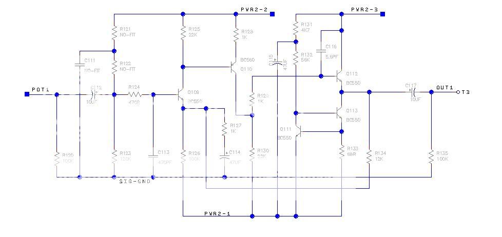
1. Remove the input coupling caps and replace them with wire links. This shouldn't be a problem in my specific case, because I know my source has output coupling caps.

2. Remove the 729 output and 321 input coupling caps. I'll be removing the pot and replacing it with a relay-switched stepped attenuator that can accommodate a DC potential across is. The question here is: what happens when the DC potentials of the 729/321 circuits combine? Bad things? Nothing? I don't know the answer to this one. At the very least, I can remove either (a) the 729 output, or (b) 321 input cap. If removing both is a non-starter, then is either a "better" candidate for removal?

3. Replace the 321 output caps with good polyprops.

Any other suggestions for reducing the coupling cap count?

Carl
 
Hi Carl,
I followed your recent AD vs SF thread with interest...as you know i bought into the AD group buy, but have not got round to building my kit (am a bit put off by my lack of experience with SMD actually so this may be up for grabs anyone?) .. do you know if Jim is doing another StarFish board as I think this is more within my comfort zone. I very much appreciate the dynamic environment you guys create here! Keep it up - cheers. Uz
 
Hi Carl - just thinking out loud here, but is it the number of capacitors or the total capacitance thats important?

So could you simple reduce the value of the 729 output and 321 input caps to say 3.3 - 4.7uF to achieve the same sonic gain?
 
Also thinking out loud. If the 729 output is only ever connected to the 321 input and vice versa (i.e. no tape output) then why have two caps in series ? Surely one cap is enough to enough to separate the DC components from each stage ? Of course I'm a complete novice, so I may be missing something quite important.

Paul
 
Usually the 729 stage output goes to the volume pot input, and the output from the vol. pot wiper goes to the input of the 321. This arrangement needs both coupling caps to stop running any DC current through the volume pot track and through the wiper contact (eg input bias current into the 321 stage), otherwise the volume control becomes noisy (all potentiometers are like this - dont run dc through them, especially the wiper!)

Carl's using an attenuator which explicitly doesn't care about this condition.

(Thinking about it Carl, even with the 729 split-railed and the output close to 0v, the input to the 321 will probably need a cap to separate the 321 input bias current from the volume pot DC condition. It can probalbly be worked-around, but that will change teh design of the stage... )
 
Thinking about it Carl, even with the 729 split-railed and the output close to 0v, the input to the 321 will probably need a cap to separate the 321 input bias current from the volume pot DC condition. It can probalbly be worked-around, but that will change teh design of the stage...

Let's have a look at the Starfish.... The 321:
gain.jpg


...and the 729...:
filter.jpg


Let's say all coupling caps are bi-polar and that resistors R121 and R122 get removed from the 321 stage. To my naive brain, that would be enough to stop DC bias current at the input to the 321? Could we then remove the 729 output and 321 input caps?
 
I guess in the above scenario with the coupling caps removed, it should be possible to also remove R120 (321 input pull-down), R101 (729 input pull-down), and R119 (729 output pull-down)?
 
Yes , you can do that, but any cumulative DC drift in the 729 then alters the operating point of the whole 321 circuit. It will work* - but it could be instructive to see what variations in DC voltage you get at the output (Q108) over a couple of days.

Anyway, if proves OK you can simply chop out R101, 102, 103, 104, 135, C2, C117 :) Just link R105 to Q112 emitter.


* providing Pwr 2-2 , 2-3, 1-2 and 1-3 are close in value ; and PWR 2-1, 1-1, 1-4 are also similar.
 
...and I'm reluctant to pull C117 unless I'm 100% sure that no DC will appear across the 321 output - there are no coupling caps on my monoblocks... :eek:
 
Looking at it again, it would appear safe to completely remove input/output coupling circuitry from the 729 boards, leaving the 321 coupling caps in place - for now. Later experimentation could be done to remove the 321 input coupling cap and, who knows, maybe even the output cap... but that's a risky one from my precious Ergo point of view!
 
Or you could just try the list of mods I sent you the other night ;)
I think you might be pleasantly surprised...


advertisement


Back
Top