Hi,
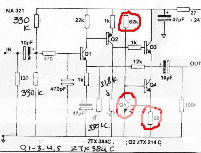
When I originally built this mod, I used (per current source, so you will need 4 or 6 times):
-Green LED
-220R resistor
-22KR resistor
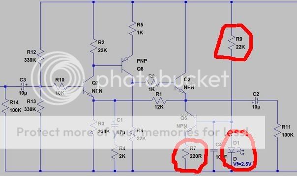
When I calculated the resistor values I used the Vf=2.5V from the datasheet - but FD is right - when you run the LED at 1mA it has a Vf of about 1.9V
I'm still running the 220R resistor - this means I am using the current source configured for approximately 6mA - and I prefer it this way.
If you want to run the current source at 9mA as naim intended, simply change the 220R to 150R.
Finally: Filtering the 22K resistor is good, but I'd suggest just implementing one mod at a time.
Adding the filter will not gain you as much as it did with the old naim current source, since the LED current source has approx 20dB better rejection anyway.
Jim.
When I originally built this mod, I used (per current source, so you will need 4 or 6 times):
-Green LED
-220R resistor
-22KR resistor
When I calculated the resistor values I used the Vf=2.5V from the datasheet - but FD is right - when you run the LED at 1mA it has a Vf of about 1.9V
I'm still running the 220R resistor - this means I am using the current source configured for approximately 6mA - and I prefer it this way.
If you want to run the current source at 9mA as naim intended, simply change the 220R to 150R.
Finally: Filtering the 22K resistor is good, but I'd suggest just implementing one mod at a time.
Adding the filter will not gain you as much as it did with the old naim current source, since the LED current source has approx 20dB better rejection anyway.
Jim.