advertisement


howto: Accelerated TeddyReg

teddy_pardo

Trade: Teddy Pardo
The TeddyReg has a long start time until the output reaches the full voltage. This delay is due to the time it takes to charge the large 33uF tantalum capacitor by a 100-150K resistor. Usually for most applications this is not a problem, but in some cases like clocks and certain DACs it causes synchronization issues. The following addition to the circuit (in blue)accelerates the charging time making it very short (less than 1 second).

TeddyRegTurbo.png


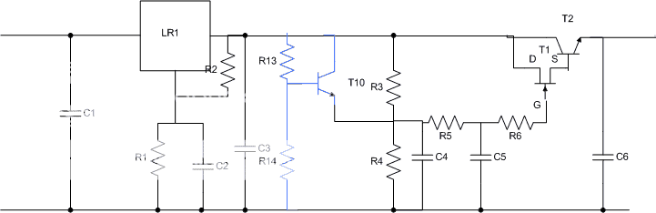
R13 is the same as R3, R14 is the same R4, and T10 is any moderate power NPN transistor (I've used BC639).

R13/R14 creates a reference voltage which is equal to the voltage on C4 when it is charged. As long as C4 is not charged T10 conducts and charges C4. As soon as C4 is charged the Vbe on T10 becomes zero and T10 no longer conducts.

This mod can easily be implemented on the TeddyReg PCBs:

IMG_1781.jpg


IMG_1782.jpg


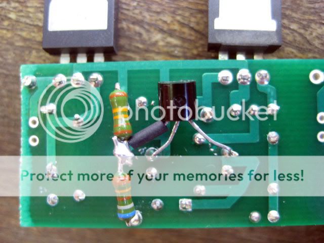
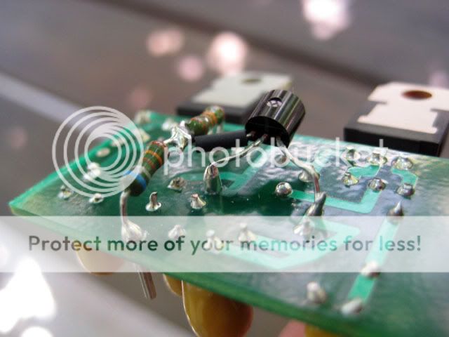
Note that I've used BC639 that has a BCE pin order, other transistors may have to be positioned differently.

Enjoy, Teddy
 
Hi Teddy...does this now mean that the Accelerated_TeddyReg will work well in my CD5 (as opposed to ALWSRs)?

and...does this make any sonic difference to the standard reg? (say in a PSU)?
 
No, sorry, i wasn't making myself clear...I've not bought any ALWSR but was planning to start the list of Acoustica-mods on my CD5 sometime soon. I was exploring using your standard Teddy (instead of the ALSWR) but was concerned about clock etc. If you've made it faster then this could be perfect as I've got some spare PCBs.
 
Nice one, thanks for posting this Teddy. I've been thinking about how to accomplish this very thing for regulating the front end of my monoblock boards. I was a little uneasy about the slow startup times, and you've just saved me (and everyone else) a job!
 
Is there an upper limit on the amount of capacitance C4 can be with this accelerator added? I am using 100uF/16V tants for C4 sometimes.
 
Teddy another way to do this would simply be a zener diode in parallel with R3. It will avalanche at switch-on then drop out of circuit once the voltage across R3 drops below the zener voltage as C4 charges further.
 
Is there an upper limit on the amount of capacitance C4 can be with this accelerator added? I am using 100uF/16V tants for C4 sometimes.

If you went mad, then the dissipation in T10 during the startup transient would be a concern, and I suppose also in the preregulator, although that should have its own thermal protection. Put T10 on a heatsink, and/or use a bigger transistor, if you want to go for really big values. I need to a more detailed calculation to work out what really big means in this context, but it is certainly more than 1000uF.
 
Teddy another way to do this would simply be a zener diode in parallel with R3. It will avalanche at switch-on then drop out of circuit once the voltage across R3 drops below the zener voltage as C4 charges further.


Brilliant idea Martin!

I assume/hope that the noise issues associated with zeners don't apply when it doesn't conduct. Right?
 
If you went mad, then the dissipation in T10 during the startup transient would be a concern, and I suppose also in the preregulator, although that should have its own thermal protection. Put T10 on a heatsink, and/or use a bigger transistor, if you want to go for really big values. I need to a more detailed calculation to work out what really big means in this context, but it is certainly more than 1000uF.

You can also add a small resistor between the T10 emitter and the capacitor. The resistor will protect the transistor and will almost not effect the acceleration (100R is still much faster than 100K...)
 
PD, TP: thanks for the tips. Martin: what are some of the design issues to consider when selecting the zener for start up of Teddy's reg? Start-up for ALWSR is also partially controlled by a zener, isn't it, heavily bypassed to eliminate noise?
 
I'd just pick a zener with a rating 1v or so more than the voltage appearing across R3 once settled. Used like that the leakage current will be 1uA or less, probably about the same magnitude as that in C4 if electrolytic. Should be no noise issue at all.

The zener in the ALWSR is a level-shifter and runs in breakdown at around 10-12mA
 
I made the accelerate mod in my 12V Teddy reg +/- pair according Tedd instructions post #1.
The + version works perfert with rapid charge and final voltage unchanged (+12V).
The - version also with rapid charge but now it measure -16V :eek: instead -12V original.
Any help is welcome.
Sergio
 
Have you used a PNP transistor or an NPN (you should use a PNP for the negative)? Make sure the pin order is correct.
 
I'd just pick a zener with a rating 1v or so more than the voltage appearing across R3 once settled. Used like that the leakage current will be 1uA or less, probably about the same magnitude as that in C4 if electrolytic. Should be no noise issue at all.

The zener in the ALWSR is a level-shifter and runs in breakdown at around 10-12mA


Hi Martin,

If 10V drop over R3, then I take a 11V zener? And the kathode is toward R4 (positive TR)?

Ronald


advertisement


Back
Top