teddy_pardo
Trade: Teddy Pardo
Some pictures of my new phono pre-amp. The preamp itself is NAC102 phono boards in which I reaplaces some components, the regulators are ALW super regulators in which I replaced the pre-regulator by VBEs (see this thread for more info). The case is a metal case which I painted in beautiful black (can't really see it in the picture, need to touch it...).
So here is how it looks like:
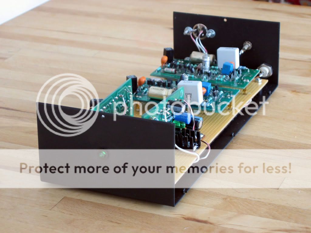
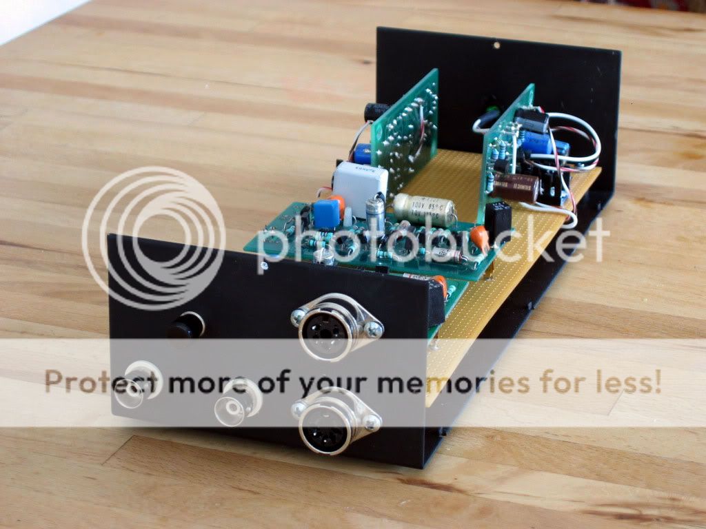
and from the back
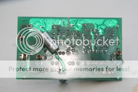
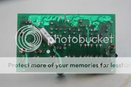
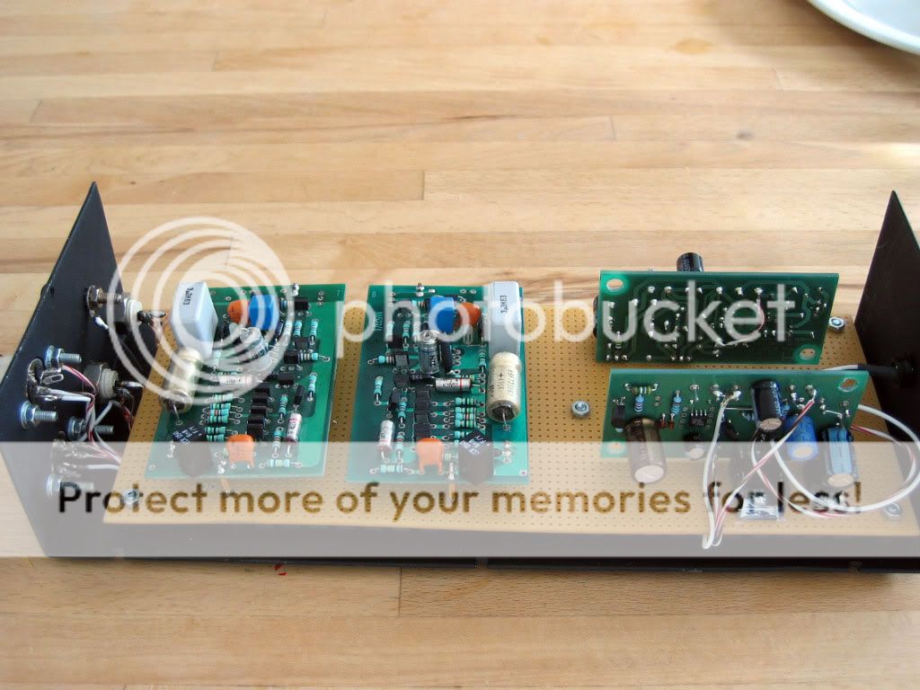
I mounted the four boards on another board on which I mounted the original NAC102 pins. Doing this allows me to quickly remove the phono boards for further modifications")
Below this board I created a star to which I connected all the ground wires.
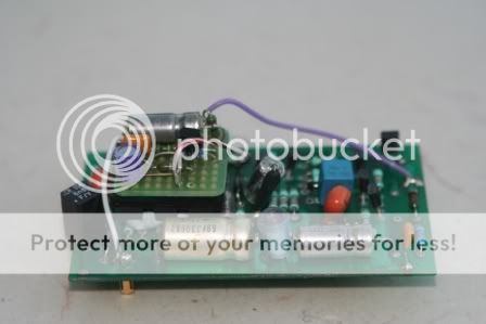
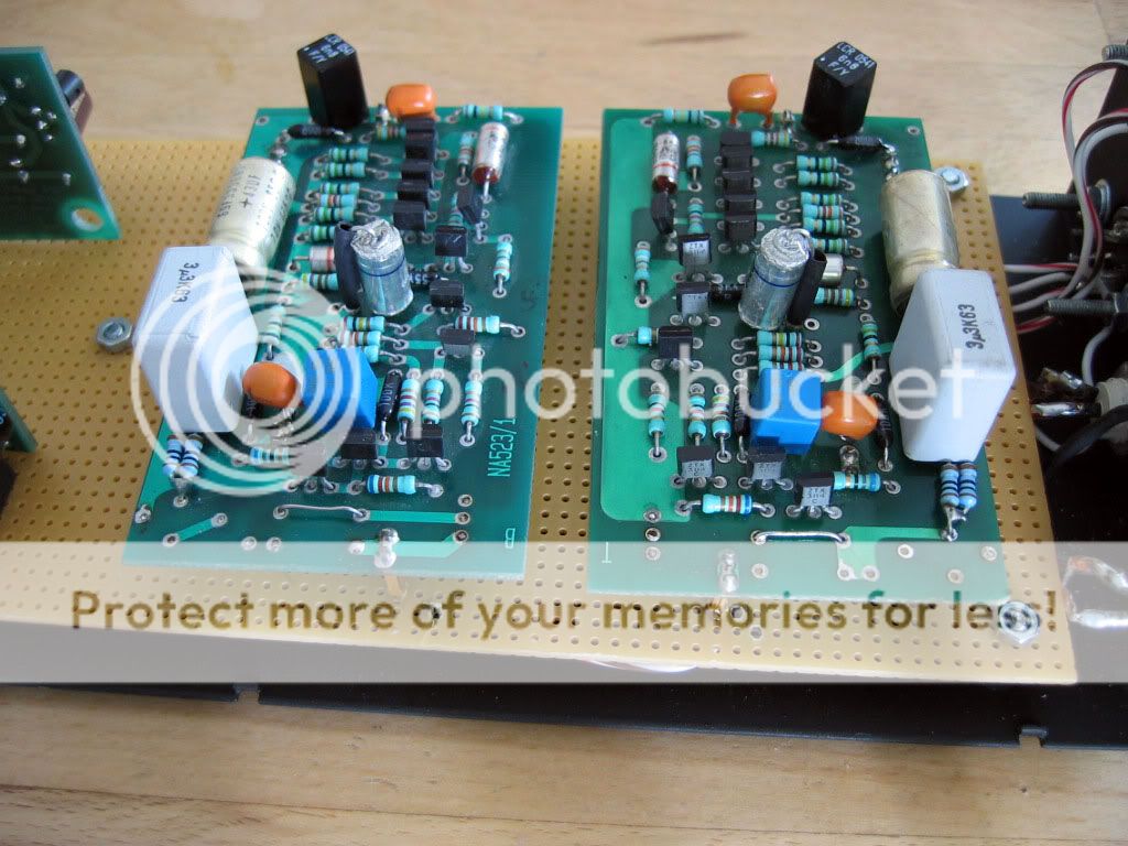
The phono boards has all the classic mods:
- Zener circuit removed
- BC128 for input/output
- 3.3uF SMR + 0.5R for decoupling
- Mil spec tantalum for feedback
- Other capacitors are polistyren where possible
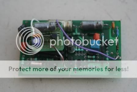
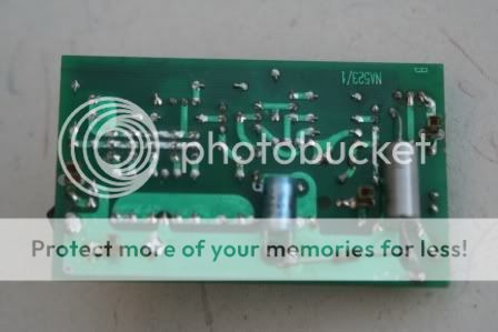
- Some critical resistors replaced by WELWYN RC55Y (note that for some reason the feedback resistors in the NAC102 are 100K and 200K instead of 64K and 100K respectively). Here is how the phono boards look:
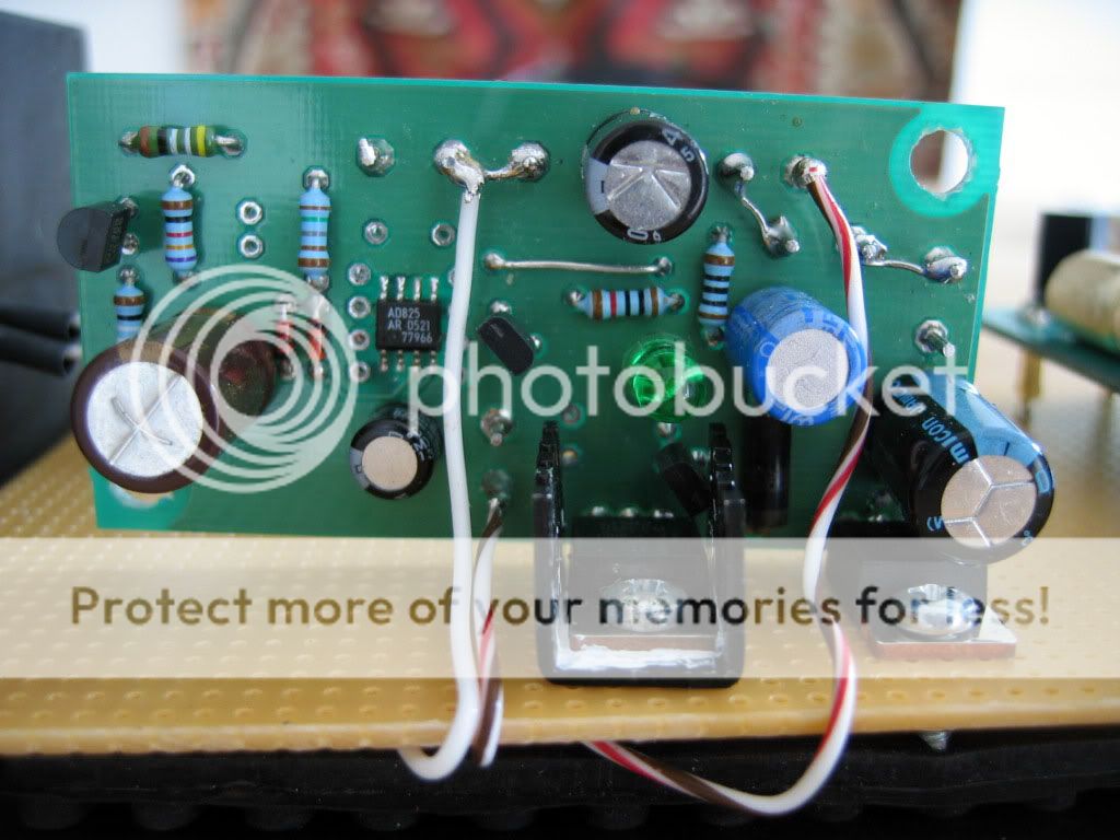
The regulators have a VBE instead of the tracking pre-regulator. This mod already sounds very good on the pre-amp boards, but here the improvement is really huge. It adds a very solid bass which was originally missing, and makes everything sound more natural and more detailed at the same time. Highly recommended here (and everywhere else...)!!!
BTW I remember that someone recently asked about replacing the resistors in the phono boards. Well, it adds some clarity but not day and night.
Yes, and last point, the PSU. With the VBE it's really not important which PSU you use, a single 32V rail from a HP deskjet does an excellent job, I compared it with a HiCap and couldn't hear any difference.
The sound of these boards is really splendid, I wish my CD would sound like this, well if fact I expect that once I install the PFM Flea and six APA627s in my CDX it will sound at least close to this...
I'm using an LP12/Lingo, LVX-III arm, with OC9 cartridge.
Teddy
So here is how it looks like:
and from the back
I mounted the four boards on another board on which I mounted the original NAC102 pins. Doing this allows me to quickly remove the phono boards for further modifications
Below this board I created a star to which I connected all the ground wires.
The phono boards has all the classic mods:
- Zener circuit removed
- BC128 for input/output
- 3.3uF SMR + 0.5R for decoupling
- Mil spec tantalum for feedback
- Other capacitors are polistyren where possible
- Some critical resistors replaced by WELWYN RC55Y (note that for some reason the feedback resistors in the NAC102 are 100K and 200K instead of 64K and 100K respectively). Here is how the phono boards look:
The regulators have a VBE instead of the tracking pre-regulator. This mod already sounds very good on the pre-amp boards, but here the improvement is really huge. It adds a very solid bass which was originally missing, and makes everything sound more natural and more detailed at the same time. Highly recommended here (and everywhere else...)!!!
BTW I remember that someone recently asked about replacing the resistors in the phono boards. Well, it adds some clarity but not day and night.
Yes, and last point, the PSU. With the VBE it's really not important which PSU you use, a single 32V rail from a HP deskjet does an excellent job, I compared it with a HiCap and couldn't hear any difference.
The sound of these boards is really splendid, I wish my CD would sound like this, well if fact I expect that once I install the PFM Flea and six APA627s in my CDX it will sound at least close to this...
I'm using an LP12/Lingo, LVX-III arm, with OC9 cartridge.
Teddy