advertisement


Coaxial digital connections

Consider a 1m cable with an inner insulator that causes the nominal internal propagation speed to be, say, 0.8 * c. Three 'trips' would mean travelling 3 metres. And would arrive 2 'trips' after the 'first arrival'.

Calculate how long that delay may be compared with, say, a single bit from an SPDIF stream of, say, 96k 24bit stereo.

Consider what that implies....

Note also that is the source *is* matched, it will eat the reflection. But again, if you assume the source and destination are say, matched to 90%, how big will the resulting signal voltage change be?

Left as an exercise for the student. :)
 
If my reckoning is right...
First part:
2/(3 * 10^8 * 0.8) = 8.3ns delay.
Last part:
90% 'acceptance' presumably = 10% rejection, so 10% goes back to transmitter and 10% of that comes back to receiver. So I reckon 1% (-40dB) although you could argue that only 90% of that gets received so -41dB. ;)
Middle part: no idea...
 
96000 x 2 x 24 = 4,608,000

Invert that to get the period for each bit sent = about 0.217 microSec = 217 nanoSec.

So, the 'three trips' error is at the 1% level in terms of signal voltage and nibbles at the first 8.3/217 th of the bit period.

the 'five trips' would be later and, erm, much smaller. Ok, a handy-wavey model, but...

In terms of the effect on normal digital value comms... 3/4th of a gnat's fart.

More detailed analysis would yeald similar conclusions. Given 1m lengths you'd need a pretty crappy source and/or receiver for it to foul up data recovery against a well guided rx clock.

Numbers all simplified above to make the point clearer. Real systems are more complex, but smarter in sensible designs. (I ignored the 0.8 velocity factor as that doesn't make a big difference to the conclusion. 9-> )

One of the reasons data/comms engineers love 'digital' is that the signals can be quite obviously degraded by 'analogue world problems' when viewed on something like a scope, yet still work like a charm.
 
I think the audiophile can smell jitter because the reflection time is in the order of the rise time, so reflections add noise to the detection of the edge. Or something. Which implies longer rather than shorter cables would be a benefit.

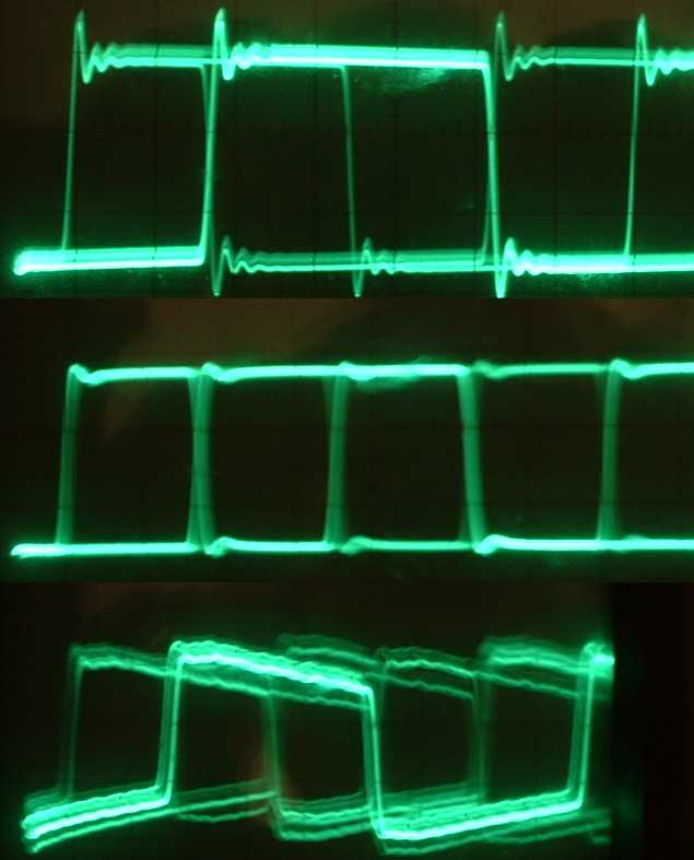
A long time ago I put a scope probe on three S/PDIF outputs I had to hand.

spdif1.jpg


Unfortunately I can recall little about the context. Upper is Linn Karik, lower is original Arcam Alpha. Middle might be a DVD player or soundcard. No idea if they are terminated (I guess yes). Scope antique 20MHz analogue. Anyway, look how much better it is!
 
Numbers all simplified above to make the point clearer. Real systems are more complex, but smarter in sensible designs. (I ignored the 0.8 velocity factor as that doesn't make a big difference to the conclusion. 9-> )

One of the reasons data/comms engineers love 'digital' is that the signals can be quite obviously degraded by 'analogue world problems' when viewed on something like a scope, yet still work like a charm.
Thanks Jim- isn't the 0.8 factor in the 8.3ns calculation? or should it go in somewhere else as well?
 
One of the reasons data/comms engineers love 'digital' is that the signals can be quite obviously degraded by 'analogue world problems' when viewed on something like a scope, yet still work like a charm.

From what I understand the problems start when you move from the IT universe - data packets - to the Audio universe - digital audio data-stream -, or when the file is rendered.
 
Last edited:
Thanks Jim- isn't the 0.8 factor in the 8.3ns calculation? or should it go in somewhere else as well?

In effect. a 1m (physical length) cable seems 1/0.8 m long if you assume the signal is moving at the speed of light in vacuum. So it increases the 'trip' times by a factor of 1/0.8
 
I think the audiophile can smell jitter because the reflection time is in the order of the rise time, so reflections add noise to the detection of the edge. Or something. Which implies longer rather than shorter cables would be a benefit.

A long time ago I put a scope probe on three S/PDIF outputs I had to hand.

spdif1.jpg


Unfortunately I can recall little about the context. Upper is Linn Karik, lower is original Arcam Alpha. Middle might be a DVD player or soundcard. No idea if they are terminated (I guess yes). Scope antique 20MHz analogue. Anyway, look how much better it is!

The lowest waveform shows how the lack of *LF* flat response can lead to 'jitter' in the apparent timing of the data *if* the RX uses zero-crossings to clean up the received pattern. In a real spdif signal there will be periods when the signal doesn't have a simple up-down-up-down-... all looking the same. The lack of LF extension in the link then 'jitters' when a zero-crossing detection discovers zero<->one boundaries.

Nothing to do with the transitions being slightly scuffed by small reflections, though.
 
One of the reasons data/comms engineers love 'digital' is that the signals can be quite obviously degraded by 'analogue world problems' when viewed on something like a scope, yet still work like a charm.

Analyzing and Managing the Impact of Supply Noise and Clock Jitter on High Speed DAC Phase Noise
Jarrah Bergeron

https://www.analog.com/media/en/ana...lock-jitter-on-high-speed-dac-phase-noise.pdf

The Effects and Reduction of Common-Mode Noise and Electromagnetic Interference in High-Resolution Digital Audio Transmission Systems
Jon D. Paul

https://secure.aes.org/forum/pubs/conventions/?elib=12438

Staying Well Grounded
Hank Zumbahlen
https://www.analog.com/en/analog-dialogue/articles/staying-well-grounded.html

Is DAC ultrasonic/RF output important?
PKane

https://www.audiosciencereview.com/.../is-dac-ultrasonic-rf-output-important.10600/
 
The lowest waveform shows how the lack of *LF* flat response can lead to 'jitter' in the apparent timing of the data *if* the RX uses zero-crossings to clean up the received pattern. In a real spdif signal there will be periods when the signal doesn't have a simple up-down-up-down-... all looking the same. The lack of LF extension in the link then 'jitters' when a zero-crossing detection discovers zero<->one boundaries.

Nothing to do with the transitions being slightly scuffed by small reflections, though.
I believe this is what the J-Test was designed to provoke, with a receiver that was susceptible.

Not been an issue for 30 or more years of course.


advertisement


Back
Top