advertisement


How to Convert a UK Naim 250 to US voltage?

Sakurama

Active Member
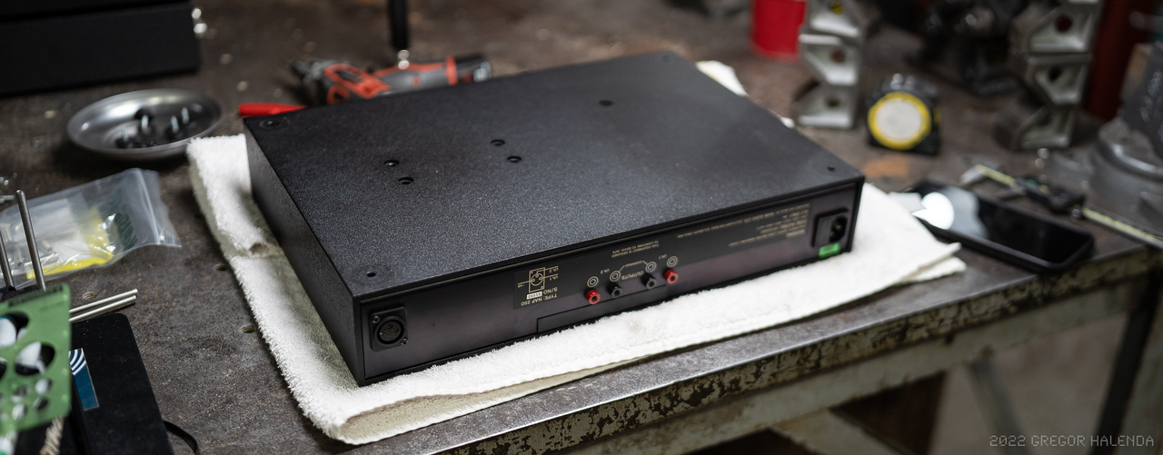
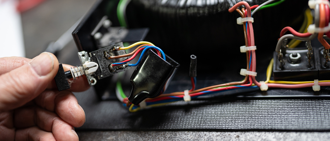
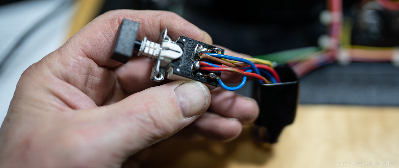
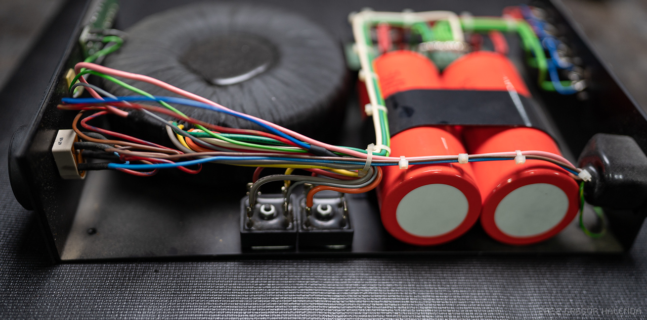
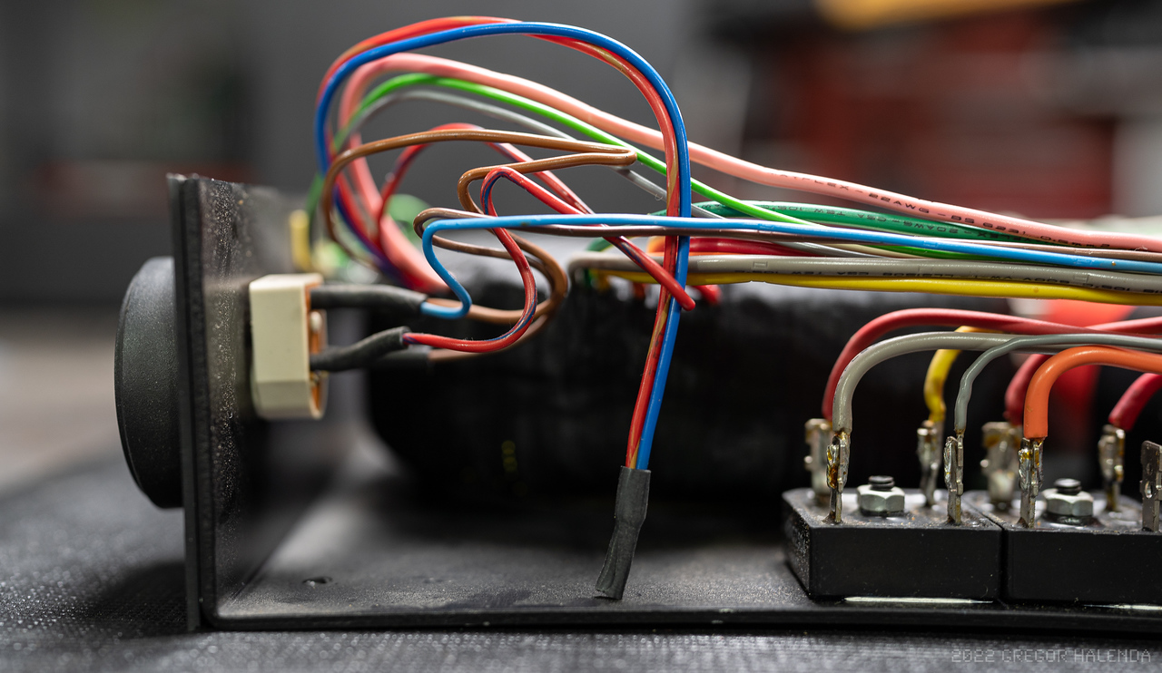
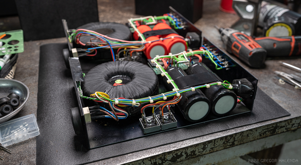
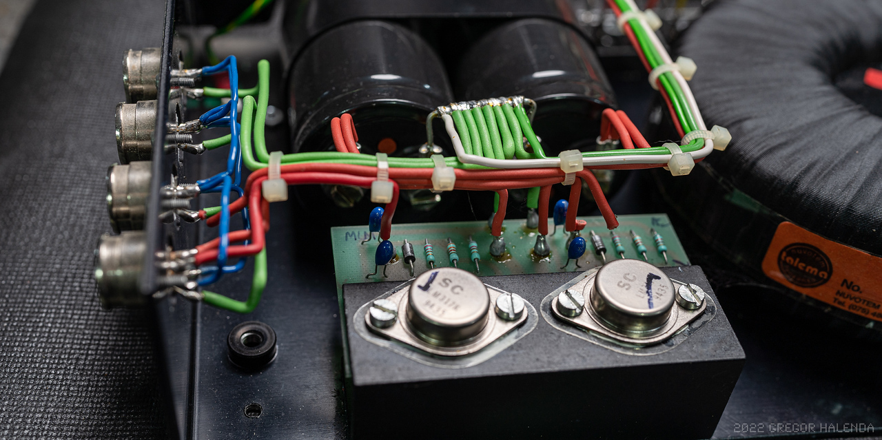
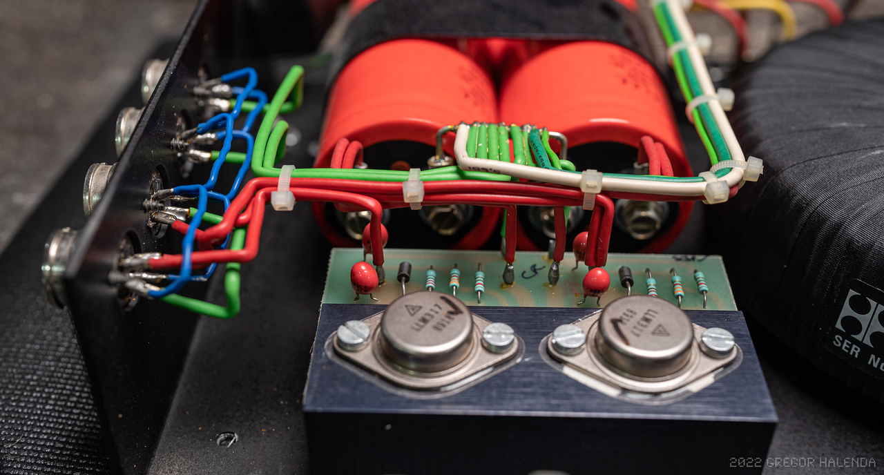
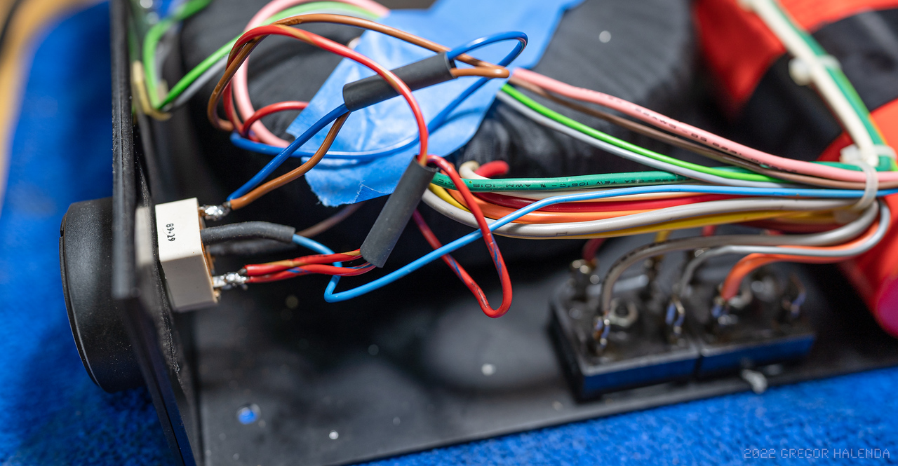
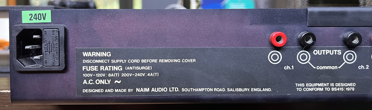
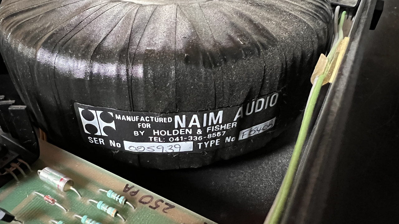
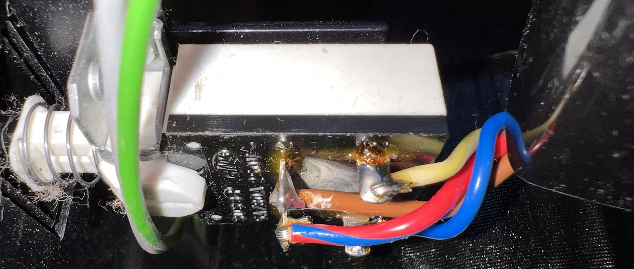
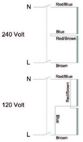
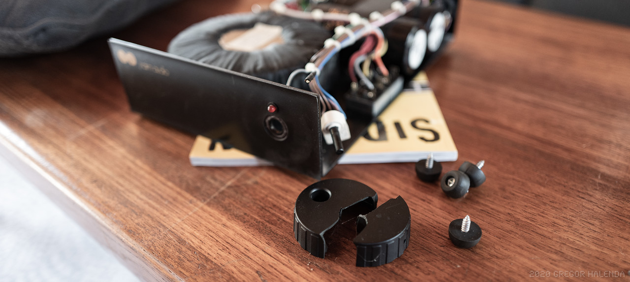
I have a HiCap and 250 from the UK that I need to wire to US spec. I'm not good at reading the wiring diagram above so I'm wondering if someone can explain it a bit more simply or perhaps show a photo of the switch. What do N and L refer to? The bars on the right side - what are they supposed to reference?

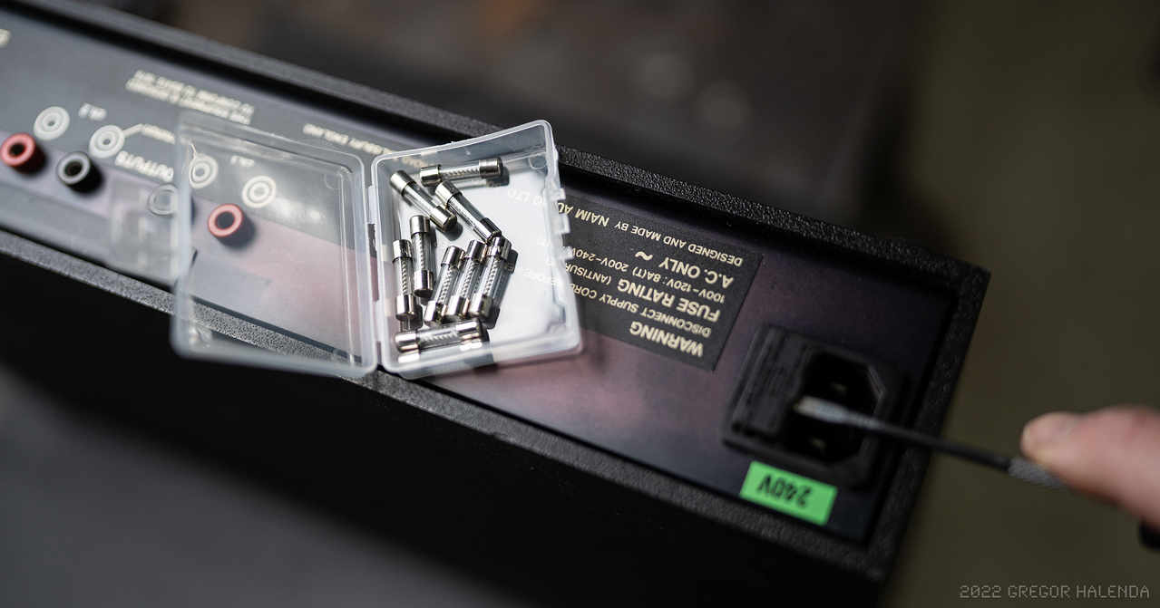
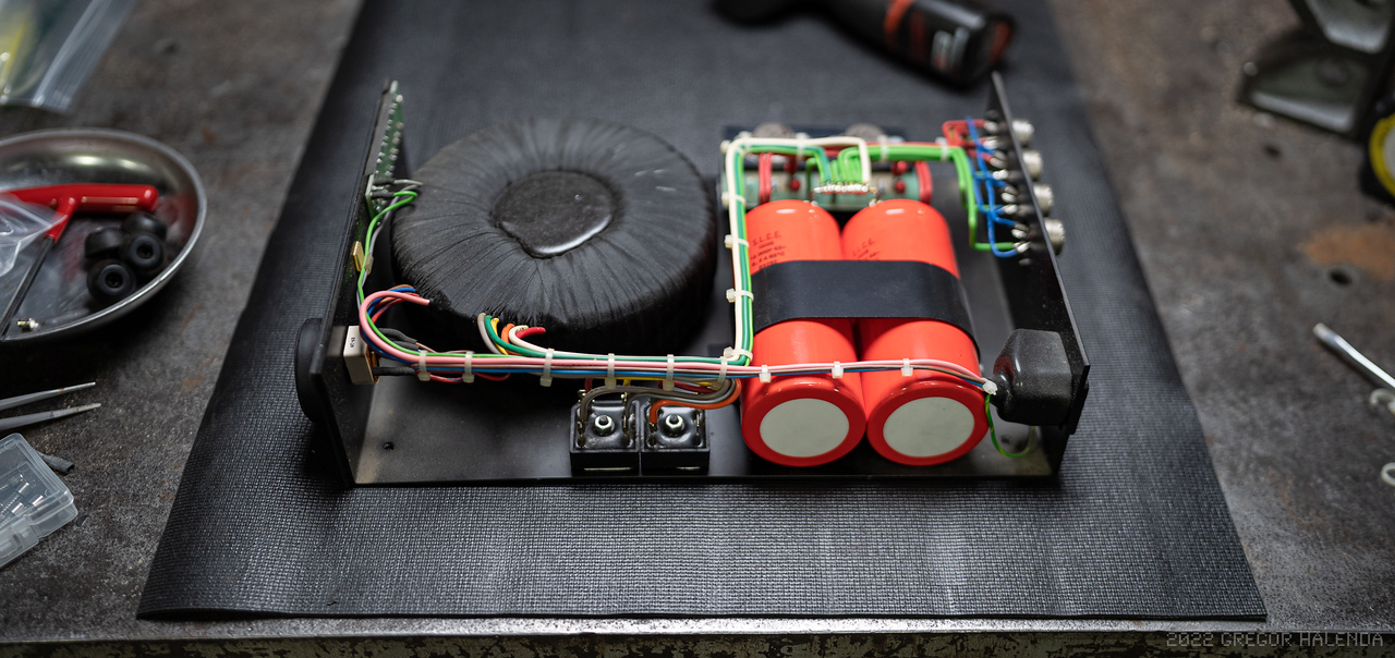
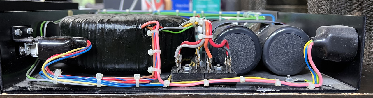
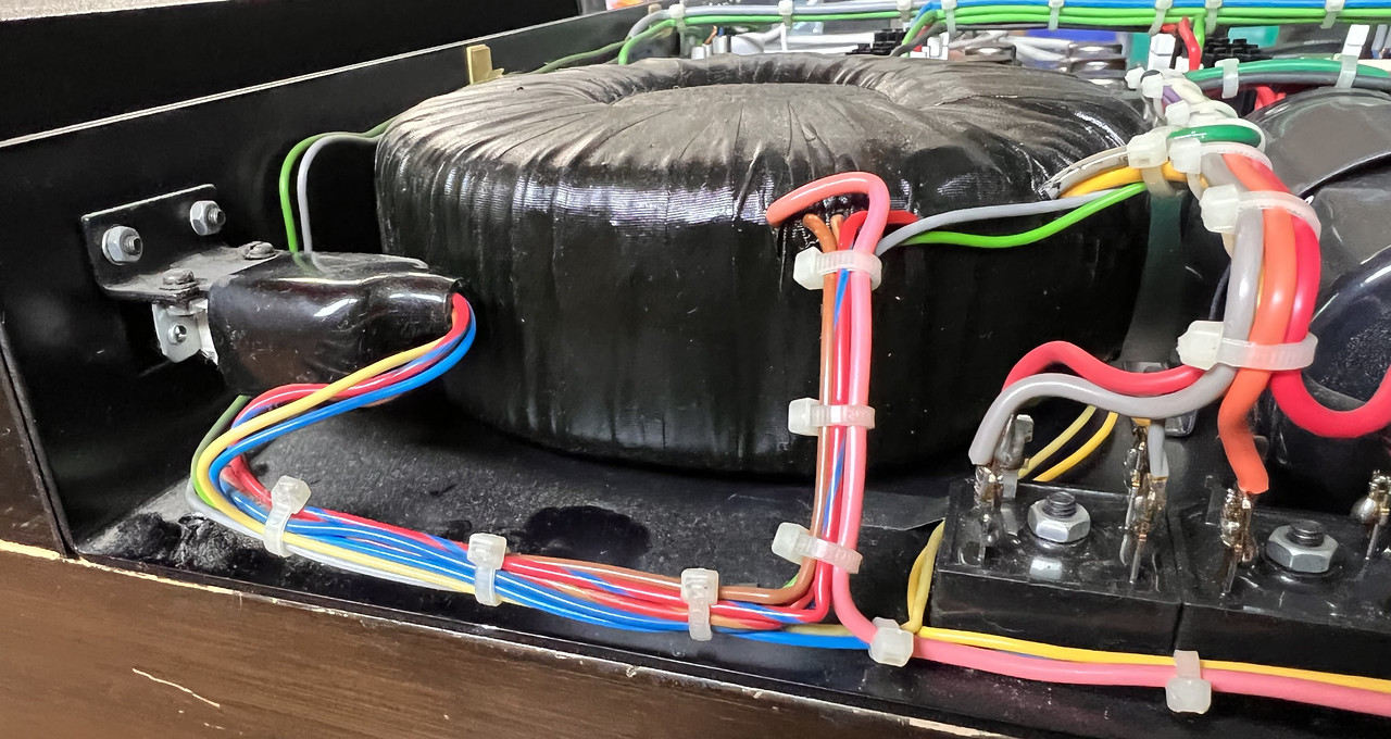
I remember when I worked at a hifi shop in college that this was a pretty simple thing to do but that was a very long time ago. I've looked at every thread I can find and have not found a single photo of this conversion so I figured I'd put some in here and then, when I understand what I'm changing, I'll show that as well.

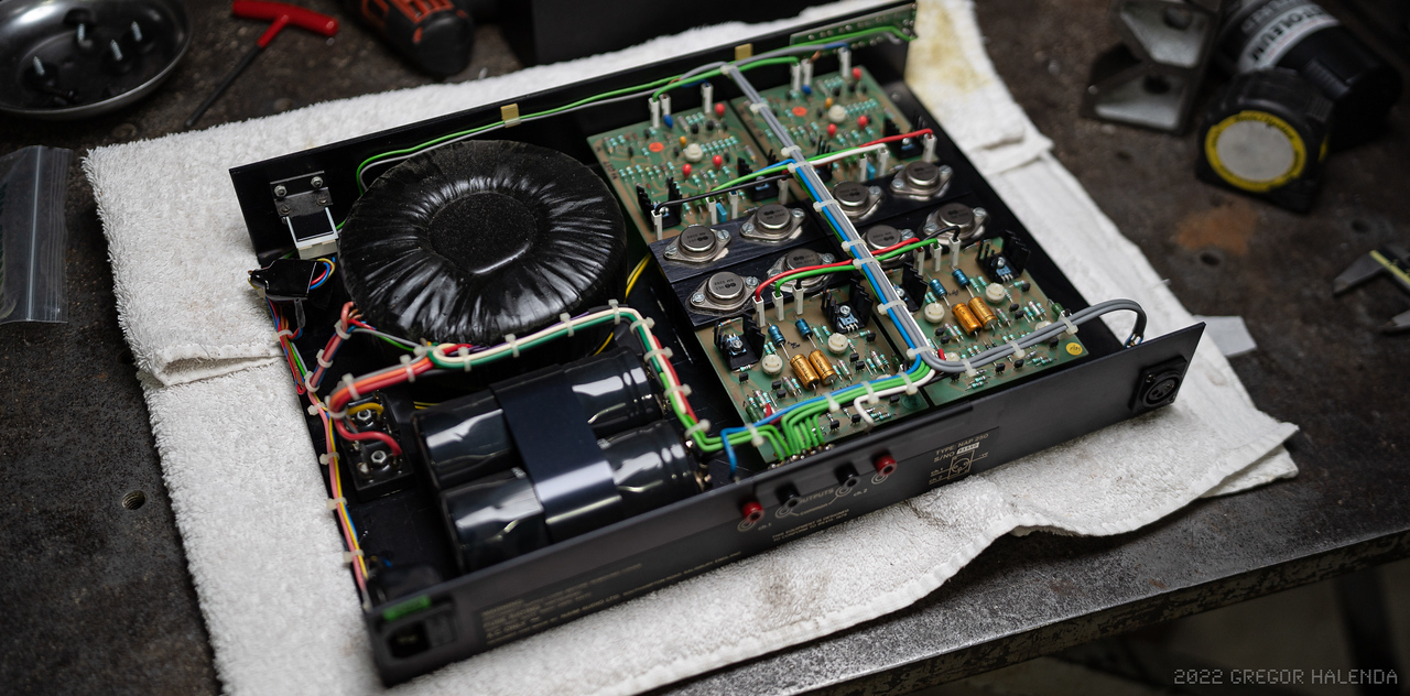
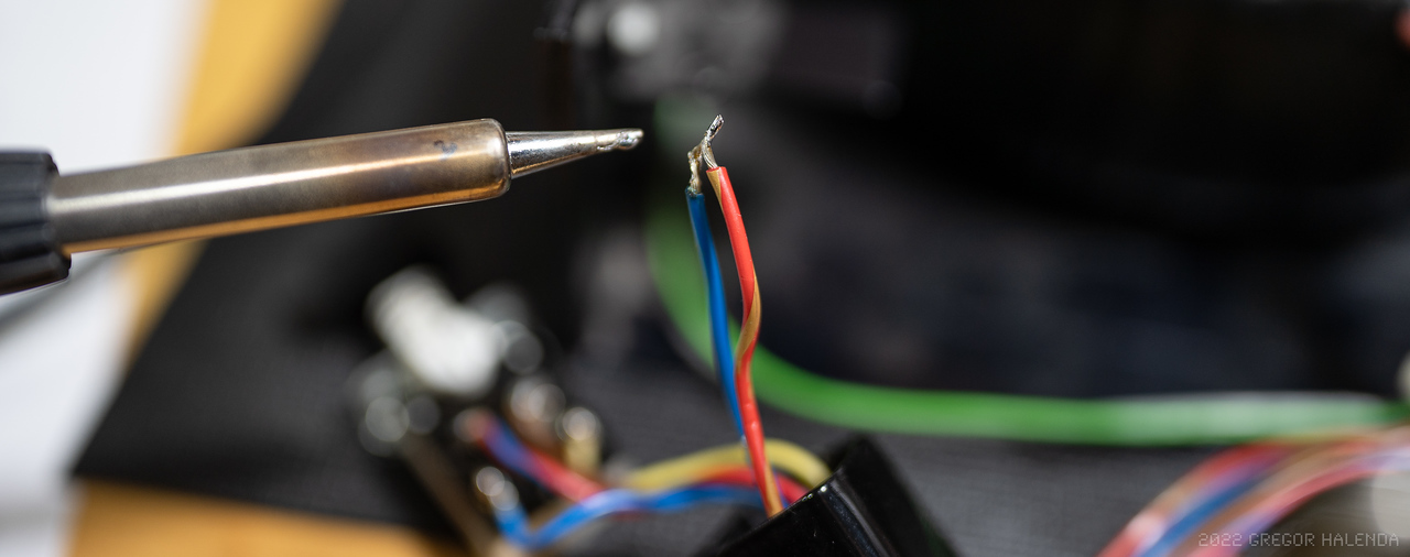
I have a second US 250 that I suppose I can open up and cross reference but I wanted to double check things here to be 100% sure before I start in with the soldering iron. And if the same applies to a UK HiCap or if there's differences please let me know as that should be next on the list.

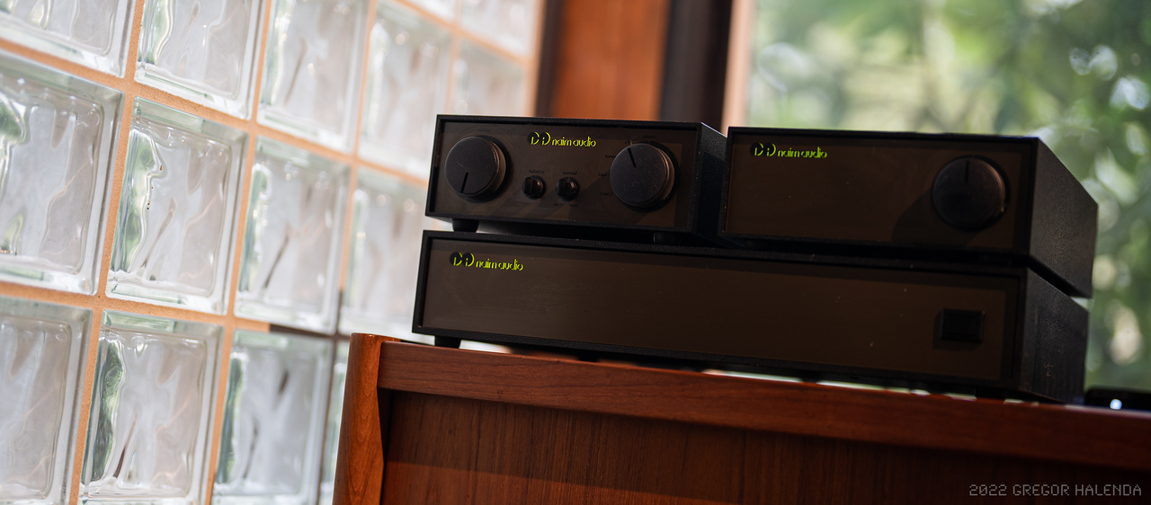
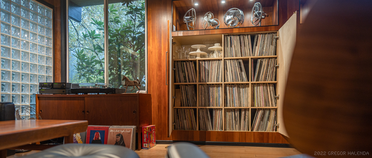
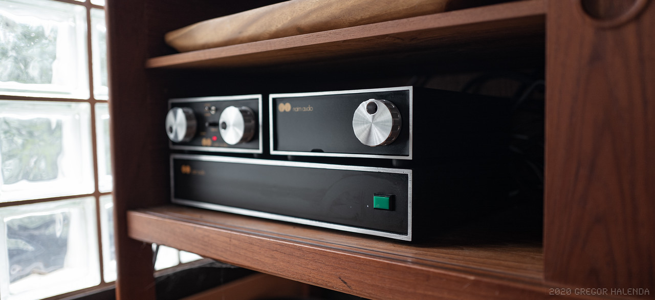
These will end up in an active SBL system - something I've wanted from when I was in college and due to some horse trading with a friend and a few ebay purchases I'm now in a position to finally make happen. So, any help here will be greatly appreciated.

Gregor
 
I have some photos but can't seem to post them...

Is there a post count minimum before you can add photos?

Gregor
 
I really don't mean to be rude or disparaging, but if you have to ask what L & N refer to then perhaps you would do better to let someone else do it. It's a pretty simple change but going from 240V to 120V means you have to solder 2 transformer primary wires to the power switch terminals and it can get a bit crowded, so it needs reasonably good soldering skills to do it right - and you could melt the switch body if you take too long doing a blob-a-job, worst case you get it wrong and blow up your kit.
I'm sure that if you print out the xfmr wiring diagram (either H&F or Talema - these are available here and other places on the web) and take it to somewhere like a local TV or electronics repair shop they could do it for a minimal charge.
 
I really don't mean to be rude or disparaging, but if you have to ask what L & N refer to then perhaps you would do better to let someone else do it.

Fair.

But I can solder. And I rewired my whole house and build motorcycle wiring harnesses. I used to work at a Naim dealer when I was in college and I probably did this conversion 30 years ago - but that was 30 years ago. I don't read schematics but yes, Live and Neutral, but that isn't particularly helpful on the switch. I suppose if I could post a photo it would be more helpful for me and also for anyone else wanting to do this.

Naim charges $295 to do this. Pretty sure it's not going to be hard but I want to be certain before I do it. And I want to have the knowledge because it's a chance to learn something and be a bit more knowledgeable going forward.

So is there a post count you have to meet before you can post a photo? I still can't post a photo.

Gregor
 
Okay, it seems I should be able to post some photos and that should get me into my happy place as I'm a photographer by trade so it's much easier for me to understand things visually rather than trying to understand a diagram. But I'd like to be schooled on that.

i-M5J5Ws2-X2.jpg

i-k7xBmZT-X2.jpg

i-dJKWSjX-X2.jpg

i-LwNzhmh-X2.jpg

i-ZHstLVX-X2.jpg


So, this is what I have on the 240v NAP 250 I have. I will take apart the US spec one to compare when it's time to make this mod but I'm still waiting for the HiCap to show up and so I'll do them both together. And I think I'll maybe dust out the 250 while I'm in there.

This is the only diagram that I've found so far and it isn't clear to me:

i-8d26R9g.jpg


So can someone explain what needs to be done here?

Thanks you in advance.

Gregor
 
It looks like the primary is made from two windings. For 240v they are connected is series. For 120v they are connected in parallel. It's a fairly common arrangement.
Cheers Robin
 
First and foremost, following these instructions is at your own risk, this to include anyone else considering such DIY work. Neither myself nor pfm/@Tony L. bear any responsibility for any losses that you may incur as a result of following these instructions (i.e. see my 'For entertainment purposes only' tag line below), nor do I warrant that such information is entirely accurate.

Converting Naim Holden & Fisher transformers from 240VAC to 120VAC usage:

All wire colours indicated within the diagram pertain to the primary side of the transformer. Brown remains on L (Live) and Red/Blue (red with blue stripe) remains on N (Neutral) at the switch. If you look closely at the wires bundled together between transformer and switch, you'll notice Blue and Red/Brown (red with brown stripe) wires bundled in and connected to one another (soldered together and shrink-wrapped rather than via a crimped butt connector), These need be desoldered from one another and then conjoined Blue to Brown and Red/Brown to Red/Blue, at the same switch terminals that Brown and Red/Blue are currently connected to, and thereby connecting the two primary side windings in parallel (rather than them being connected one after the other in series as they are currently).​

As mentioned by @Loz828 in post #3 above, you'll want to be hot and quick with the soldering iron else end up needing a new switch.

NOTE: The mains inlet fuse at the back will also need be changed out to a T8A/250V ("T" for anti-surge), says so right on the label round back there.
 
Last edited:
First and foremost, following these instructions is at your own risk...

As mentioned by @Loz828 in post #3 above, you'll want to be hot and quick with the soldering iron else end up needing a new switch.

NOTE: The mains inlet fuse at the back will also need be changed out to a T8A/250V ("T" for anti-surge), says so right on the label round back there.


Thank you, thank you Craig. That is very simple now.

i-XL66Xmh-X2.jpg


I didn't notice the co-joined wires in the loom as they were tucked in the bottom. Now things make sense. And how nice of them to leave enough wire to make the whole job easy. There's no reason to desolder anything so just tin and piggy back these to the correct terminals.

I will do this next week when I'm back from my job and the HiCap is here. I'm guessing the HiCap is the same thing then.

Thank you. I'm much closer to an active system now.

Gregor
 
You're welcome, Gregor.

If the HI-CAP also has an H&F transformer then all will be the same, except for the rotary switch being somewhat more delicate.

Be aware that a later model with Talema/Nuvotem transformer will be quite different. Same concept but different colour codings plus a complication that Naim may not have connected these the same way round as the maker suggests. Long story short (no pun intended), Naim found these to be inconsistent wrt winding direction and therefore test each one and somehow code them as to which end goes where for optimum performance. This according to a former Naim employee who posts on here.

Anyway, let us know what you've got once you have it and we'll go from there.

BTW, I really enjoyed your website, and took the liberty of setting my desktop background to your R1200S stunt rider shot. Looks fab on my big Mac!

Craig

P.S. I've just cracked the Talema code, so no worries whichever you end up with.
 
Last edited:
Be aware that a later model with Talema/Nuvotem transformer will be quite different. Same concept but different colour codings plus a complication that Naim may not have connected these the same way round as the maker suggests. Long story short (no pun intended), Naim found these to be inconsistent wrt winding direction and therefore test each one and somehow code them as to which end goes where for optimum performance. This according to a former Naim employee who posts on here.
This might be worth a separate thread. I have Nuvotem transformers in my ncc based amp so could be very useful info to me and others too.
 
You're welcome, Gregor.

If the HI-CAP also has an H&F transformer then all will be the same, except for the rotary switch being somewhat more delicate.

BTW, I really enjoyed your website, and took the liberty of setting my desktop background to your R1200S stunt rider shot. Looks fab on my big Mac!

Craig

Hi Craig,

Thanks much for this. I'll post up some photos when I get into it and hopefully not botch any of the soldering.

That shot you're talking about was when I was the official stunt rider for BMW and traveled around the country riding prototype motorcycles for their ad campaigns. It was a lot of fun but I wanted to be shooting those ads so shortly thereafter I started shooting for BMW, Ducati and REV'IT! and still do to this day. That was also the beginning of my fabrication journey which mostly involves building motorcycles but I've done a bit with my hifi too. Here's my older chrome bumper kit that one of the big knobs (which I always loved and would swap out when I could find the knobs) finally broke and I decided to fix once and for all. Now of course the switch broke so I'll need to replace that, but I think the new knobs play well with the chrome edged kit.

i-RNQv4Cw-X2.jpg

i-FDpb36z-X2.jpg

i-LNcthxQ-X2.jpg

i-7GkVDV9-X2.jpg

i-NWQpztc-X2.jpg


I need to do a bit of work replacing the switch on the hicap and then my old silver bumper stuff will probably end up as a second system in the new addition I'm planning to do next year. I enjoy giving the older gear a new life and now that I'm back into hifi I'll be coming up with some more projects for the system as time allows.

But I'll report back when I get into the hicap as well. Many thanks again!

Gregor
You're welcome, Gregor,

I foresee an interesting off-season sideline for you. Thinking raw (with clear coat), in addition to grey and/or black anodizing.

Cheers,
Craig
 
Thank you, thank you Craig. That is very simple now.

i-XL66Xmh-X2.jpg


I didn't notice the co-joined wires in the loom as they were tucked in the bottom. Now things make sense. And how nice of them to leave enough wire to make the whole job easy. There's no reason to desolder anything so just tin and piggy back these to the correct terminals.

I will do this next week when I'm back from my job and the HiCap is here. I'm guessing the HiCap is the same thing then.

Thank you. I'm much closer to an active system now.

Gregor

Good stuff - I think you've got the idea now, yes just cut the zip ties to open up the wiring loom and you have found where the 2 primaries are linked in series for 240VAC, that splice in the loom needs to be cut and then the 2 wires wired onto the switch. Naim are really neat with their wiring, so don't cut them short leave them as long as possible, that way you can switch between 120VAC / 240VAC as often as you need to. As someone else already mentioned don't forget to change the fuse. As I said before - be careful soldering multiple wires onto the switch. Good luck :)

Also re the Talema transformers, I have a feeling that the coloured dot stickers mean something about which way that particular transformer was chosen to be wired, but I haven't seen enough of them to be sure about that - any input on this MJS?
 
Hello again.

As promised here's some photos of the process so hopefully it will help others down the road.

i-XQxnKS6-X2.jpg


Euro NAP 250 on the bench. Remove the screws and feet. I'm using a thick towel to allow me to tip the unit up onto the back face and then lift the casing off. I was nervous to chip or crack the front facade plastic.

i-jNZ4MWP-X2.jpg


The beautiful layout inside. I've already pulled the boot off the power switch on the left side...

i-b4MqprJ-X2.jpg


The two wires, blue and red/brown are buried inside the loom surrounded by the other wires so they can't be seen until you start to clip the zip ties back one by one. The shrink wrap can be pulled off the two wires but first I threaded them through the black switch cover.

i-6pSJ2BT-X2.jpg


I set me solder iron for 399C (750F) and tinned the iron and touched it to the pair and they came apart quickly.

i-HRk6CcF-X2.jpg


I didn't want to desolder the original wires so I bent the leads and tucked them under the wires and then on top of the post so they would be pulling down and melt into the other wires. I tinned again, touched the iron and fed a little solder to get it to flow and once it did I took off the heat - all in all about 1-2 seconds. The blue wire went to the brown wire post and the red/brown wire when to the red/blue wire post.

i-HKTPdG5-X2.jpg


I didn't have white zip ties but hopefully the black ones will still sound good. All tidy again.

i-MtSXJ7j-X2.jpg


Once it's all buttoned up I swapped out the 4amp fuse for the 8 amp slow-blow fuse. The fuse is hidden inside the mains lead plug.

i-Gpd7tGR-X2.jpg


And with the fuse changed I swapped out my other 250 and swapped in the new one and crossed my fingers...

...and it's amazing! Even without time to properly warm up it sounded great. Many thanks for the help here, I'm halfway there.

i-k8tFWHp-X2.jpg


So the HiCap is a little different with the rotary switch...

i-q6RbLb6-X2.jpg


...the paired wires are buried very deep inside the harness, surrounded by the other wires so as to be invisible. You can just see them in the photo above.

i-BQT6gB4-X2.jpg


So a couple of questions on the rotary switch above having not worked with one before. The wires seem to be soldered onto posts and then covered with shrink. I thought perhaps they were post/sleeve but it appears not.

Since there are two browns and which does the blue go to? My guess would be the brown from the transformer and the red/brown goes to the red/blue. Do I need to cut the shrink tube and desolder the original lead and then pair them and resolder? Or cut the shrink, wrap the new wire around the original post/wire and solder?

It's after midnight here so I'm going to call it a night with one success and one in process.

Thanks again for the help.

Gregor
 
Hmm, more questions this morning than last night.

I opened up my other hicap to see which wires needed to be joined and the post arrangement of the switch is different but it seems it's the ones from the transformer. So the blue would go to the brown from the transformer and the red/brown would go to the red/blue from the transformer. Here's a photo of the second HiCap.

i-MrRsHV2-X2.jpg


But then while looking at the second HiCap, the one I've been using in my system for a few months now, there's a wire that has been snipped.

i-9r3WJgM-X2.jpg


It's the +ve to socket 3 on the hicap and it seems quite deliberate as it's snipped cleanly at the post on the board and then again at the terminal at the plug.

The Hicap has functioned fine and I've not noticed anything strange. What is the purpose of this? The second Hicap - the one from the UK - that wire is connected to +ve on terminal 3.

i-d88Zqm9-X2.jpg


Can anyone explain that? Should I replace that wire and remake the connection?

Thanks for any advice or help here.

Gregor
 
i-k8tFWHp-X2.jpg


So the HiCap is a little different with the rotary switch...

i-q6RbLb6-X2.jpg


...the paired wires are buried very deep inside the harness, surrounded by the other wires so as to be invisible. You can just see them in the photo above.

i-BQT6gB4-X2.jpg


So a couple of questions on the rotary switch above having not worked with one before. The wires seem to be soldered onto posts and then covered with shrink. I thought perhaps they were post/sleeve but it appears not.

Since there are two browns and which does the blue go to? My guess would be the brown from the transformer and the red/brown goes to the red/blue. Do I need to cut the shrink tube and desolder the original lead and then pair them and resolder? Or cut the shrink, wrap the new wire around the original post/wire and solder?

It's after midnight here so I'm going to call it a night with one success and one in process.

Thanks again for the help.

Gregor
Nice work, Gregor.

You've guessed correctly, definitely the newly extracted blue goes with the brown from the transformer (to the transformer, really).

As to wire connection method, anything that puts less heat into what might be an unobtainium (as replacement) switch the better, IMO.

Craig
 
Hmm, more questions this morning than last night.

I opened up my other hicap to see which wires needed to be joined and the post arrangement of the switch is different but it seems it's the ones from the transformer. So the blue would go to the brown from the transformer and the red/brown would go to the red/blue from the transformer. Here's a photo of the second HiCap.

i-MrRsHV2-X2.jpg


But then while looking at the second HiCap, the one I've been using in my system for a few months now, there's a wire that has been snipped.

i-9r3WJgM-X2.jpg


It's the +ve to socket 3 on the hicap and it seems quite deliberate as it's snipped cleanly at the post on the board and then again at the terminal at the plug.

The Hicap has functioned fine and I've not noticed anything strange. What is the purpose of this? The second Hicap - the one from the UK - that wire is connected to +ve on terminal 3.

i-d88Zqm9-X2.jpg


Can anyone explain that? Should I replace that wire and remake the connection?

Thanks for any advice or help here.

Gregor
Socket 3 is intended to include a single rail 24V+ve feed for use with none dual-rail NACs, or NAXO 2 or 3.

I'm not sure why this would have been disconnected. Makes no difference otherwise, unless one absentmindedly jams a NAP DIN4 in there which will likely let some smoke out.
 
Hi Craig,

Thanks for your help. Both the 250 and Hicap are now in the system and making music and sound great.

i-cKhVSW2-X2.jpg


i-wJqXR8p-X2.jpg


I was about to resolder a new wire into that Hicap for the +ve lead but I was able to find some older literature that mentioned that the socket 3 is only used to power older equipment (and this was literature from the 90's) and the connection guides I've been able to find to set up the SBL's as active don't use that socket at all so I'm going to just leave it.

i-tgTcbDJ-X2.jpg


I just finished building a Linn LP12 setup jig to facilitate some updates on the turntable and I'm not sure now what I want to do first. On deck now it to build a stand for the turntable so I may do that first and then just start adding the updates one by one. Mostly I'm really enjoying listening to music again.

i-tc77r3H-X2.jpg


Thanks for the help here - it was an easy job but one I didn't want to screw up.

Gregor
 
I really don't mean to be rude or disparaging, but if you have to ask what L & N refer to then perhaps you would do better to let someone else do it. It's a pretty simple change but going from 240V to 120V means you have to solder 2 transformer primary wires to the power switch terminals and it can get a bit crowded, so it needs reasonably good soldering skills to do it right - and you could melt the switch body if you take too long doing a blob-a-job, worst case you get it wrong and blow up your kit.
I'm sure that if you print out the xfmr wiring diagram (either H&F or Talema - these are available here and other places on the web) and take it to somewhere like a local TV or electronics repair shop they could do it for a minimal charge.
Hi,
I want to change my nap300 from 230 to 115. It's a Talema transformer and the wires are different colors than the 250. I found Brown (live) and white (neutral) on the power switch. The 2 bundled transformer wires are purple and blue. Which colors do the purple and blue get attached to?
Thanks


advertisement


Back
Top