
I’ve just seen this thread and am feeling slightly guilty of, at least in part, instigating this build! I’ll be watching closely now to see how Mike finds the 686 when it’s finished. I actually used SMPS supplies in mine, I’ve toyed with the idea of some linear supplies but it’s so good already that I suspect its design means it’s very unfussy about the supplies used and that it might be a waste of time.
You are using an out of date browser. It may not display this or other websites correctly.
You should upgrade or use an alternative browser.
You should upgrade or use an alternative browser.
Neurochrome Modulus-686 Build Underway
- Thread starter Mike Hanson
- Start date
Mike Hanson
Trying to understand...
Thanks for poking your head up and taking the blame.I’ve just seen this thread and am feeling slightly guilty of, at least in part, instigating this build! I’ll be watching closely now to see how Mike finds the 686 when it’s finished. I actually used SMPS supplies in mine, I’ve toyed with the idea of some linear supplies but it’s so good already that I suspect its design means it’s very unfussy about the supplies used and that it might be a waste of time.
 In all honesty, I misread your original post as one from James. Given my happiness with the Ergo IX (playing beautifully as I write this) and my upcoming PFM Special build, I was swayed to look into the Modulus-686. Once I was down the rabbit hole, I liked what I saw (and appreciated that Tom Christiansen/Neurochrome was here in Canada). I can be a be a bit impetuous, and I guess this is a suitable example of that. By the time I found out that it was your message, rather than James', that spurred me on, I had already ordered the modules.
As for the power supply, Tom assured me that an SMPS would work fine, but he did note that the recommended one sometimes has issues with whining (which I experienced myself when I tried to use a pair of smaller Mean-Well supplies in an earlier build of my own). Consequently, I decided to go with a tried and true linear supply (although I've never actually tried AnTek transformers and Power-686 boards before
).I'll keep plunking away at it over the next couple of weeks, and will keep everyone posted accordingly.
Mike Hanson
Trying to understand...
Yeah, I'm liking the idea of that more than the Dremel. I've just ordered one of these:A coping saw works extremely well for cutting out iec shapes. Just drill a hole in each corner to start.
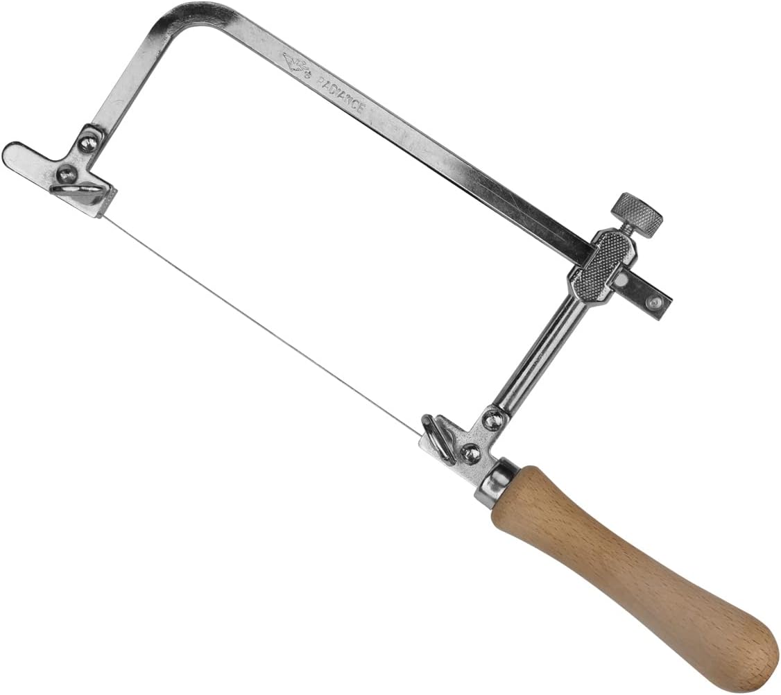
Aluminum should be soft enough to work with it. If not, I'll try something else and save this for a possible tiling project.
a.palfreyman
pfm Member
Just need a fine metal blade. At least 3 teeth for the thickness you are cutting and light pressure so it doesn't snatch / grab in relatively soft aluminium.
James Evans
Bedroom Bodger
God I hate the metalwork bit! And the wiring for that matter, even more than the sodding soldering
Mike Hanson
Trying to understand...
Soldering is fine, as long as stuff holds still.God I hate the metalwork bit! And the wiring for that matter, even more than the sodding soldering
Metalwork can be a hassle, but the right tools make all the difference in the world. My drill press is very cheap, so I hate cutting holes larger than a half-inch, which is why I was pleased to find the knockout punch for the Neutrik connectors.Of all the things, I enjoy the wiring most. Figuring out the best route, determining the right length, crimping, cable tying, etc.
S-Man
StrivingON
Yeah, I'm liking the idea of that more than the Dremel. I've just ordered one of these:
Aluminum should be soft enough to work with it. If not, I'll try something else and save this for a possible tiling project.
That has an advantage over the type I suggested... you don't need such a big hole to start with!
Mike Hanson
Trying to understand...
I suppose you could cut 22mm hole, then notch out gaps for the nibs, but they actually recommend a 24mm hole: https://www.neutrik.us/media/8496/download/nl4mp-3.pdfArent eutrik 22mm plus nibs?
Once I punch the main hole, I insert the connector and use it to mark the screw hole positions. Also, I've settled on using their MFD mounting frames, rather than my own nuts.
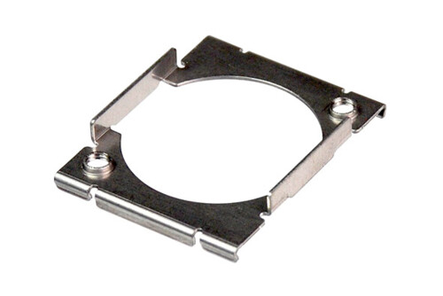
It's much less fiddly, and the cost is minimal.
Here's a lesson I learned: I originally intended to have the connector flange inside the back panel. The MDF frame wraps around the back of the flange, and the screws reach in from the outside. Unfortunately, it didn't matter how low the profile of the screw was, I couldn't easily insert the plugs into the connectors, even though it made for a very clean look:
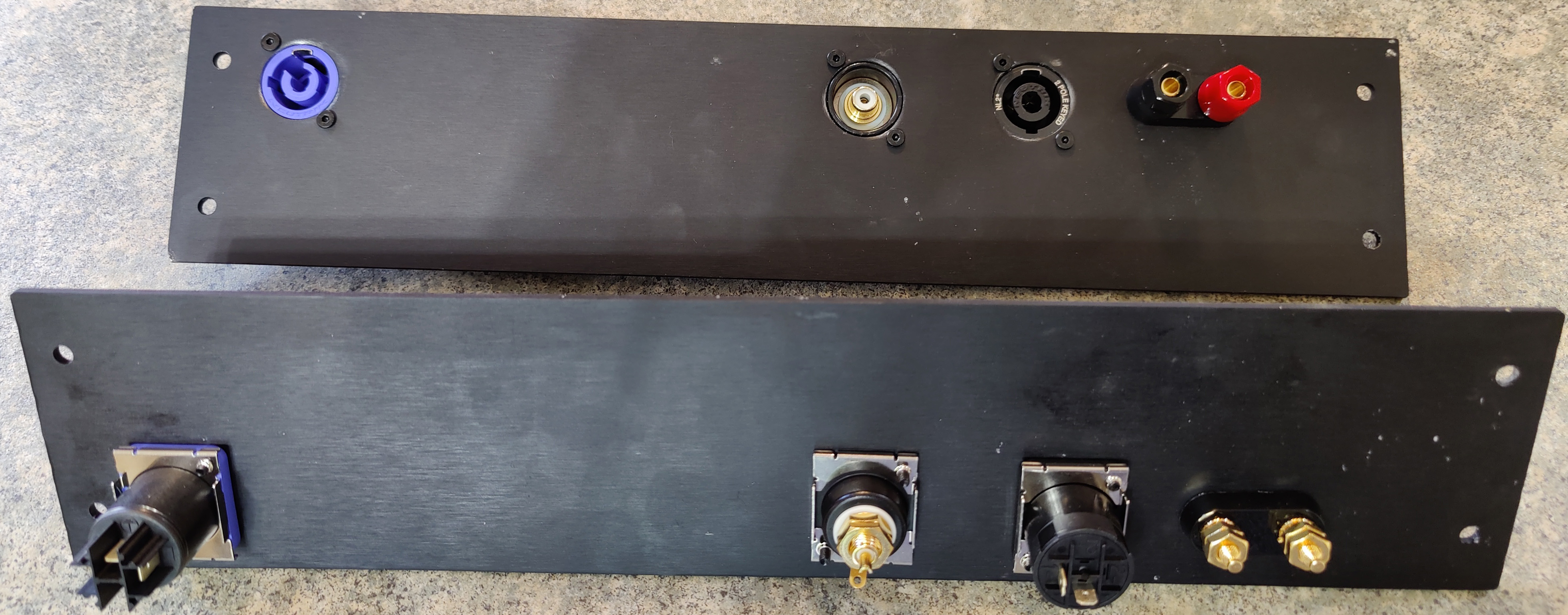
Note that I use 3mm aluminum panels, and it may have worked with 1mm steel panels.
Instead, I position the connector flange on the outside, and use the MFD frame as a matched pair of nuts on the inside. You'll see that on this build (although I ran out of MFDs, so used washers+nuts on the RCA connectors):
Mike Hanson
Trying to understand...
Yup, that was the original intention. I guess it makes a slightly bigger hole than necessary on the other side, but sometimes that's helpful, in case I don't get the mounting holes in exactly the right place. I'm getting better with practice, but I don't expect to get it perfect without a CNC (which I don't plan to get).Ah, rear face fits...
Mike Hanson
Trying to understand...
BTW, speaking of tools, I've been using a cheap automatic center punch, which was driving me bonkers. I just plumped for a Starrett 18A and it's so much better!
Pete MB&D
Pete Maddex, the one and only!
I only enjoyed the woodworking on my Neurochrome build.
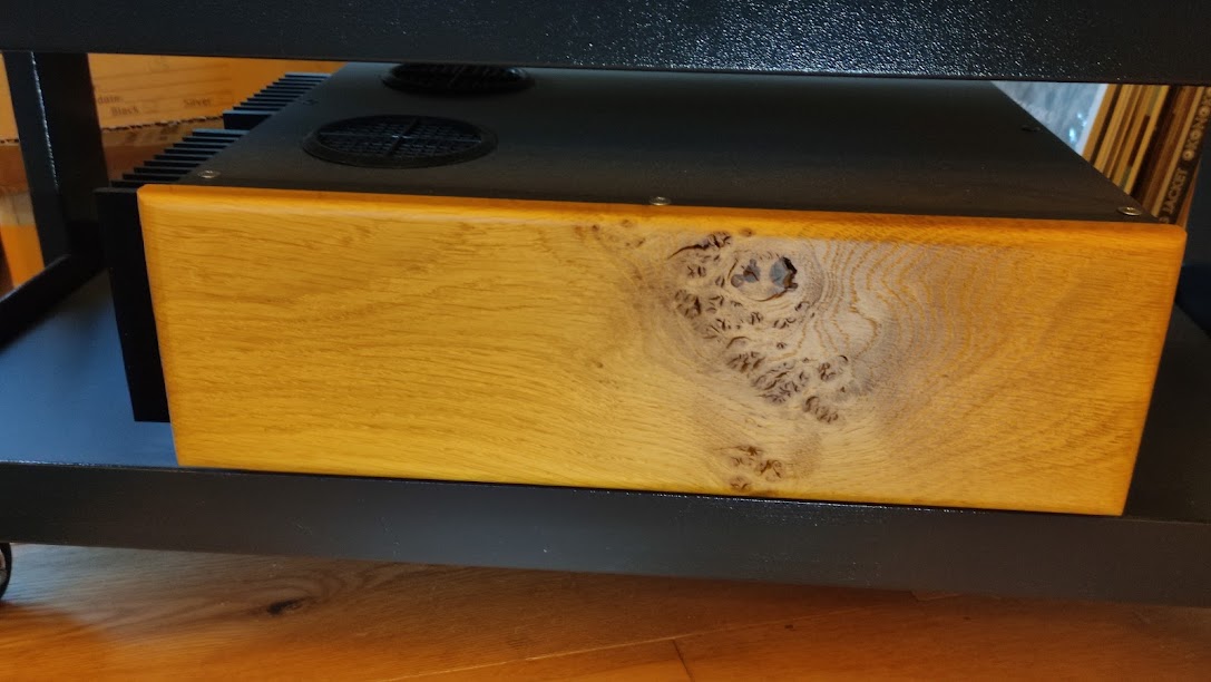
Wood and HiFi made for each other.
 Starfish preamp by Pete Maddex, on Flickr
Pete
Mike Hanson
Trying to understand...
I'm making progress. I started with the rear plate, drilling the ½" holes for the fuse holder and Keystone binding posts, and the pilot holes for the Neutrik connectors and IEC C-14 power input. I used a Diamond Wire Saw and file to finish the IEC hole, which worked much better than the jigsaw I tried last time. Then I started to use the 24mm knockout punch to do the Neutrik holes, and promptly stripped my punch. It was cheap, so I've ordered another (two). Unfortunately, it's going to take 1-3 weeks to arrive.
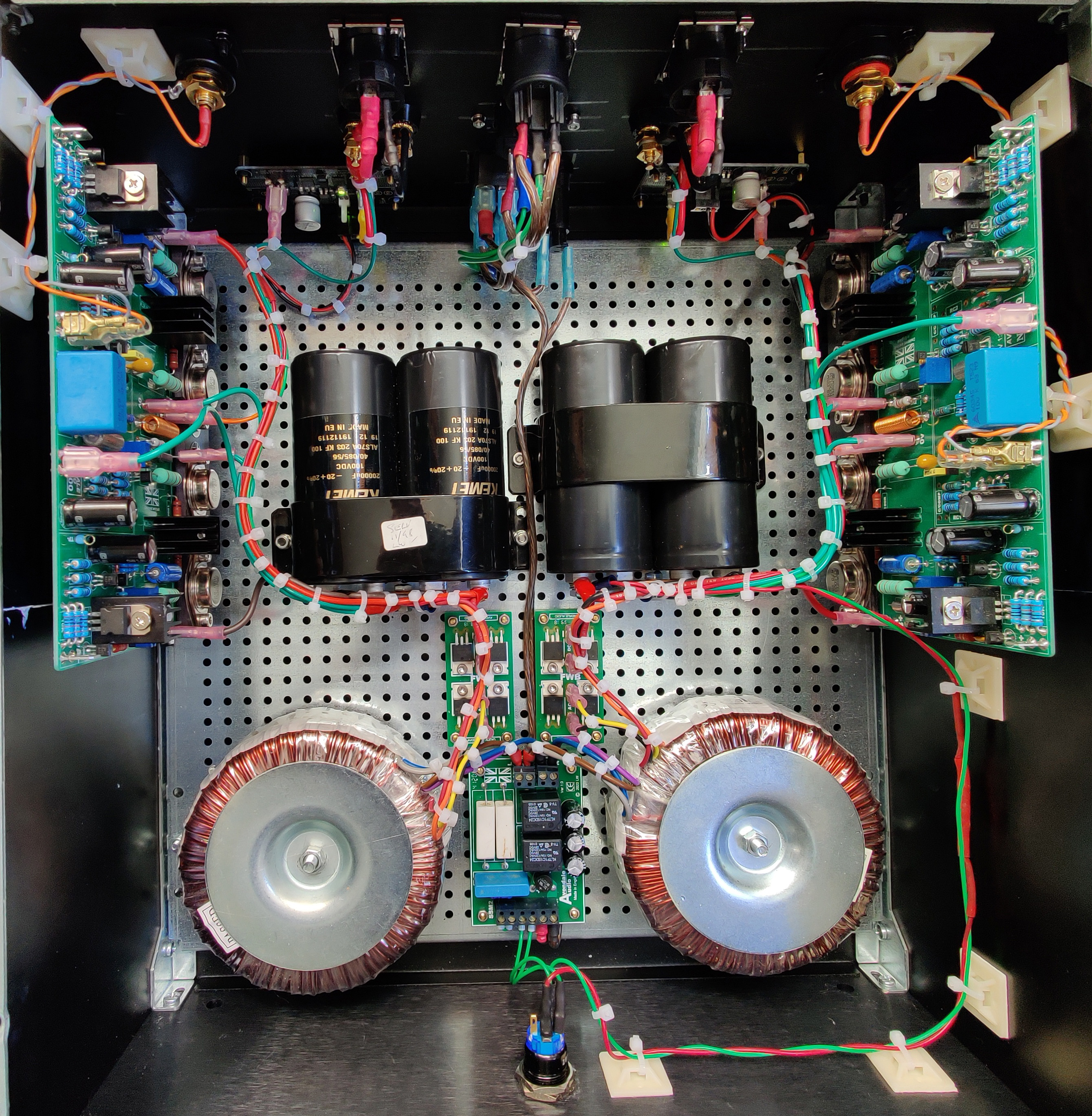
I've proceeded on with the base plate, drilling all the holes for the Intelligent Soft Start, two Power-686, and two transformers, plus three chassis grounding holes (with sanding), and four holes for the feet. I've just finished putting all that together:
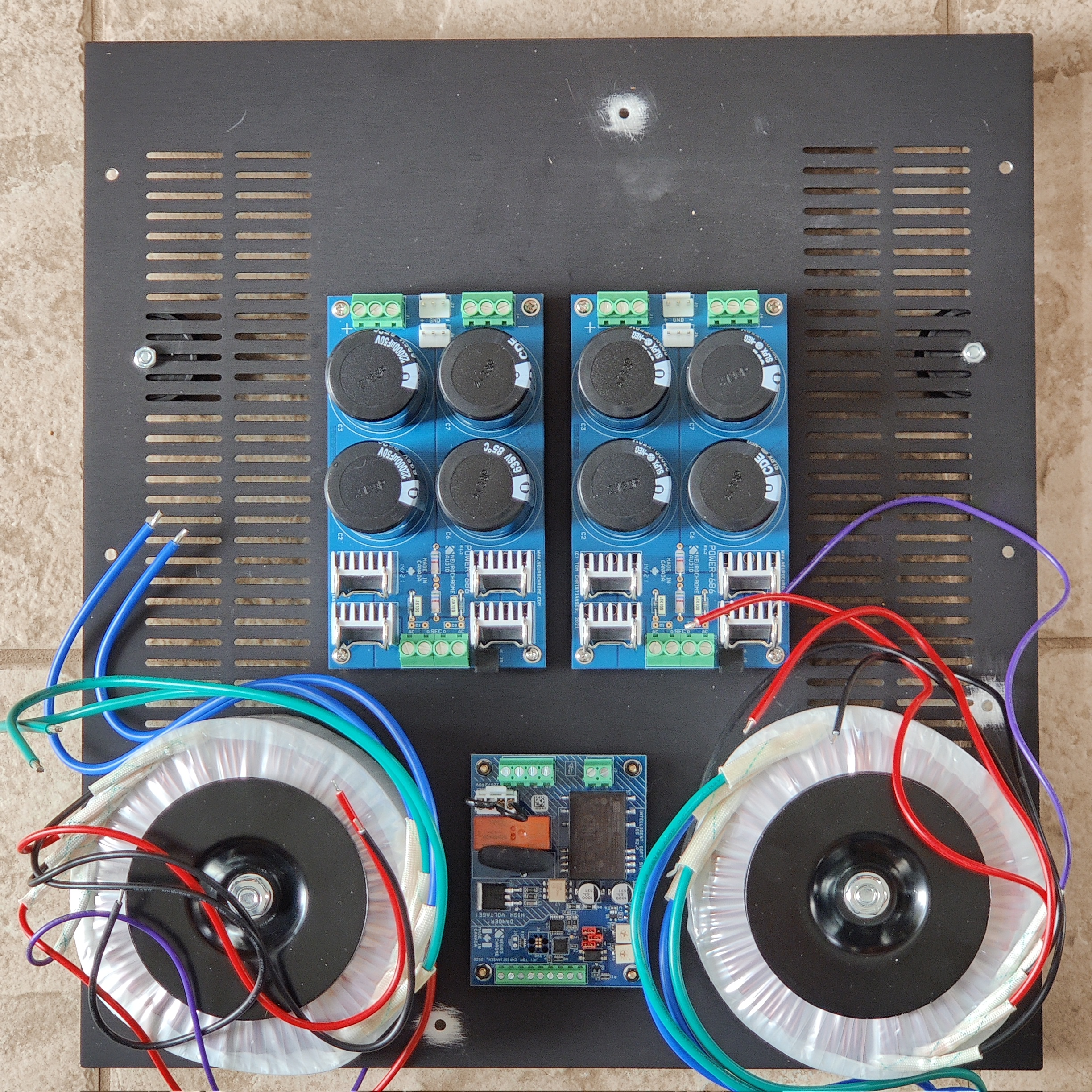
I just noticed that the left transformer needs to be rotated 90°CCW. From what I understand, toroids are good at minimizing EMI, but they have a bit of "turbulence" at the wire exit points. Therefore, I'm trying to aim those two points away from the Modulus-686 units, which will be sitting quite close to the transformers.
Additionally, the preferred position for the transformers has them mounted to the "grill" area of the Dissipante, and I'm concerned about the strength of those little slats. I had an old 1mm steel plate from an earlier Modushop Pesante build, so I hacked a couple of chunks off to use as large washers to spread the force over a wider area. That should improve vertical strength, but the horizontal strength still depends on two little grill slats, which were lessened further to make way for the bolt hole. Consequently, I'll probably use some epoxy to affix the "washer plate" to the bottom, and I might even fill the grill gaps to solidify it further. That should help with horizontal stresses.
Finally, the front feet are near the corners (hidden behind the transformers), but the rear feet are a fair distance from the back. Here's my thinking:
I've proceeded on with the base plate, drilling all the holes for the Intelligent Soft Start, two Power-686, and two transformers, plus three chassis grounding holes (with sanding), and four holes for the feet. I've just finished putting all that together:
I just noticed that the left transformer needs to be rotated 90°CCW. From what I understand, toroids are good at minimizing EMI, but they have a bit of "turbulence" at the wire exit points. Therefore, I'm trying to aim those two points away from the Modulus-686 units, which will be sitting quite close to the transformers.
Additionally, the preferred position for the transformers has them mounted to the "grill" area of the Dissipante, and I'm concerned about the strength of those little slats. I had an old 1mm steel plate from an earlier Modushop Pesante build, so I hacked a couple of chunks off to use as large washers to spread the force over a wider area. That should improve vertical strength, but the horizontal strength still depends on two little grill slats, which were lessened further to make way for the bolt hole. Consequently, I'll probably use some epoxy to affix the "washer plate" to the bottom, and I might even fill the grill gaps to solidify it further. That should help with horizontal stresses.
Finally, the front feet are near the corners (hidden behind the transformers), but the rear feet are a fair distance from the back. Here's my thinking:
- The case is 400mm deep (front to back), which is larger than any of my shelves. Therefore, I didn't want the feet to extend beyond the reach of a typical 300mm shelf.
- The transformers represent a significant proportion of the weight, so the unit is front heavy. It's never going to tip backwards, because of the shifted position of those rear feet.
- Just for kicks, I may add a fifth foot at the back center, utilizing the grounding hole. The main four are antivibration feet from Modushop, and I don't have a spare of that type. Therefore, I may use some Sorbothane to create a spacer so the non-magical foot ends up at the same height. Or I may just use a normal foot, for sliding the case back into the shelf area, then lift it a bit when the actual rear feet encounter the shelf edge.
sq225917
Bit of this, bit of that
Have you mounted the traffo bolt with a nut and a big washer clamping it to the chassis? I always find this better than just relying on the top nut for bolt tension. Of course you need fully threaded bolts to do this, but it does keep bolt tension independent of traffo clamping force which allows for way more fine tuning of optimum clamping pressure.
Where did you get a dem?Really enjoying reading this, I am about to get a 686 in my system, superb sound when demonstrated to me.
BugBear
Mike Hanson
Trying to understand...
That's a good idea, although it would still ultimately depend on the strength of those two little half-slats (half what they were earlier, due to the bolt hole). I think this bold isn't fully threaded, but I probably have one that is (or can easily get one).Have you mounted the traffo bolt with a nut and a big washer clamping it to the chassis? I always find this better than just relying on the top nut for bolt tension. Of course you need fully threaded bolts to do this, but it does keep bolt tension independent of traffo clamping force which allows for way more fine tuning of optimum clamping pressure.
For that matter, I was pondering how to determine what "tight enough" was, regarding pressure on the transformer. I haven't done any research, but I'm sure that one wouldn't want to clamp down on it too hard.