
You are using an out of date browser. It may not display this or other websites correctly.
You should upgrade or use an alternative browser.
You should upgrade or use an alternative browser.
Pics of your HackerNAP builds please
- Thread starter Puggie
- Start date
They look sensible money and decent stock in a month (fingers crossed), so may well go with them.I'm using the MJL3181a which are apparently really good!
Not quite finished the build yet, so can't vouch for them, but lots of good reports on the net.
https://cpc.farnell.com/on-semiconductor/mjl3281ag/transistor-npn-to-264/dp/SC06820?ost=Sc06820
337alant
Negatively Biased
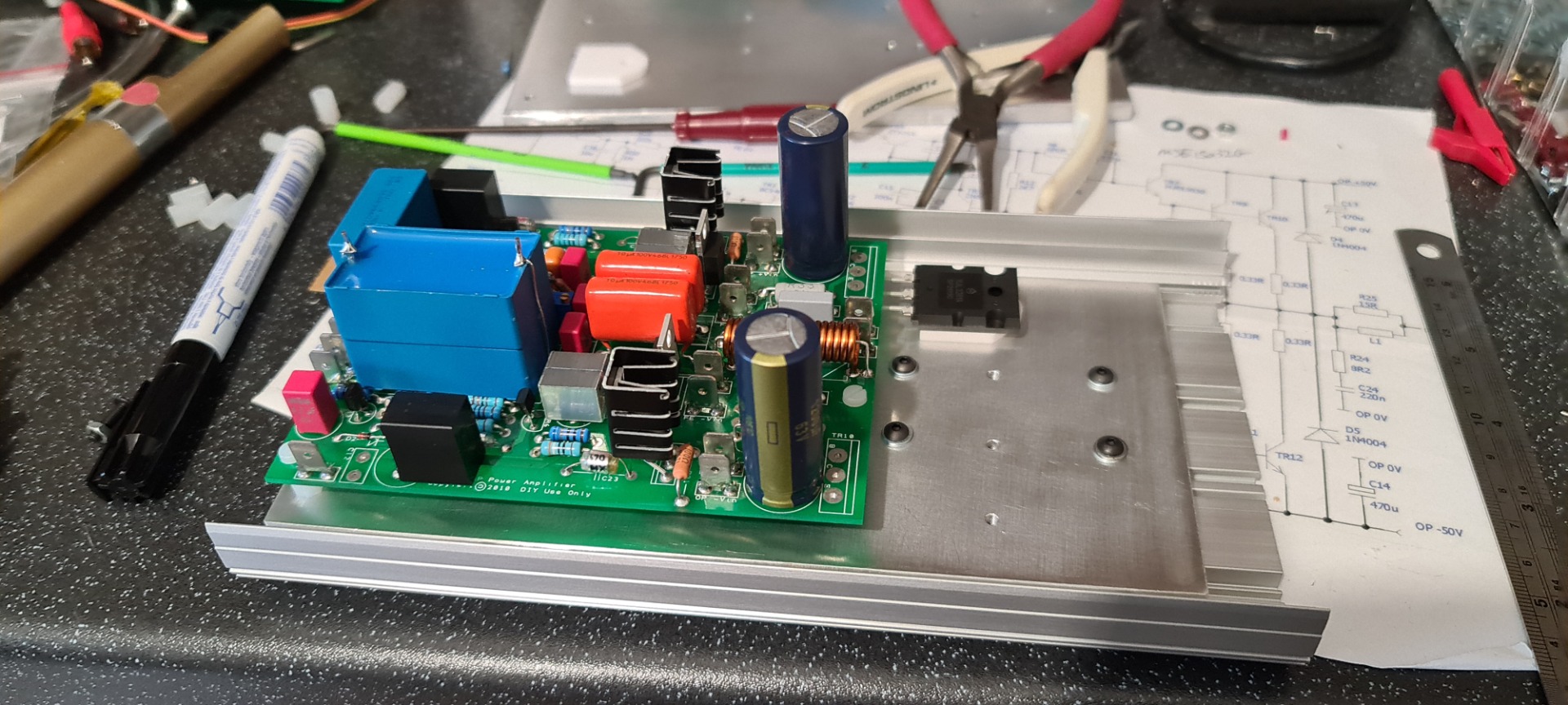
Hi GrogI'm hoping my small case will have enough heatsinking.
The boards are attached to a 6mm thick 100mmx200mm heat spreader, which is bolted to the outer aluminium extrusion.
I've also put TR5 under the board so much closer to the heatsink than in the usual position.

Did you use thermal paste between the side heat sinks before bolting them together, it will help with heat dissipation
Alan
337alant
Negatively Biased
Hi GrogI also have some NJW21194G which are a reasonable substitute.
I have a number of these that I pulled from some work amplifiers with faulty input stages.
I can send a few, for a charity donation.
Probably take a few days to get round to test them
Let me know if that helps.
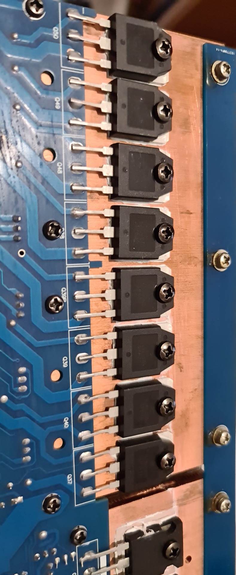
Why did you not turn the legs of the transistors through the holes in the PCB so you get better contact with the actual copper track instead of bridging the interface between the transistor and PCB with a solder bridge ?
Alan
Grog
pfm Member
Hi Grog
Why did you not turn the legs of the transistors through the holes in the PCB so you get better contact with the actual copper track instead of bridging the interface between the transistor and PCB with a solder bridge ?
Alan
Those are the old boards I'm recycling transistors from.
They are "professionally" built.....
Grog
pfm Member
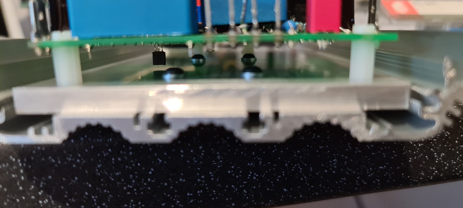
I havn't currently, but not yet bolted together, just a dry fit.Hi Grog
Did you use thermal paste between the side heat sinks before bolting them together, it will help with heat dissipation
Alan
I've found where the contact area is small the thermal paste really helps, but with a large contact area it makes very little difference.
Where is everyone sourcing their transformers?
Has anyone tried a switch mode supply? I'm looking at the meanwell PID-250D, two of those would give 46-52v rails ( output is trimmable) and a 4.75-5.25 rail to put on top, giving a potential 50v pair and 55v pair of rails.
Tnyone tried similar?
Has anyone tried a switch mode supply? I'm looking at the meanwell PID-250D, two of those would give 46-52v rails ( output is trimmable) and a 4.75-5.25 rail to put on top, giving a potential 50v pair and 55v pair of rails.
Tnyone tried similar?
Mike Hanson
Trying to understand...
I built something similar: https://pinkfishmedia.net/forum/posts/4357478/Where is everyone sourcing their transformers?
Has anyone tried a switch mode supply? I'm looking at the meanwell PID-250D, two of those would give 46-52v rails ( output is trimmable) and a 4.75-5.25 rail to put on top, giving a potential 50v pair and 55v pair of rails.
Tnyone tried similar?
If you read through that thread you'll see I had trouble with the lowered powered supplies. As for stacking mixed voltages to get different rails, I'm not sure how well that would work.
Interesting that you can make it work. I'll look in more depth later. I've had good luck with Meanwell supplies, they seem good quality. This is what I was thinking of:

This should work, all outputs are isolated so they should be able to float on each other. That gives me rails for both pre and power and they are adjustable by 10%.
Might look at capacitance multipliers for smoothing rather than brute force cap banks.
This should work, all outputs are isolated so they should be able to float on each other. That gives me rails for both pre and power and they are adjustable by 10%.
Might look at capacitance multipliers for smoothing rather than brute force cap banks.
Mike Hanson
Trying to understand...
Given both 5VDC and 48VDC supplies can provide similar current (5A and 4.7A respectively), it may just work. I'm assuming that you're planning to use the ±48V rails for the output stage, and ±53V rails for some type of regulated input supply. If so, I would be concerned that demands from the output stage (the shared ±48V portion) would affect the cleanliness of the power for the combined ±53V supply.
Yep that's pretty much the plan. Would look to some smoothing on the 53v rails, either a CLC filter or capacitance multiplier before I feed to HackerNAP front end to help smooth any noise.
Very similar you your Avondale setup you linked to, but I'm guessing they don't have the higher voltage separate front end (I'm not very clued up on the different Naim style amps).
I really wanted to do monoblocks, but this would probably be more than enough grunt for the stereo pair. The 48v rails will do 8.4A for 10sec overcurrent.
Mike Hanson
Trying to understand...
I would be somewhat concerned about putting smoothing caps on the outputs of the MW supply. I recall that it could cause the supply to get rather confused. (I can't remember where I read that.)
Also, the maximum current draw when a big transient hits could result exceed 5A (briefly).
So far I'm basically happy with mine, but I've not really used it in anger. It's on the "pleasant" system in my family room, which usually plays at fairly low volumes.
Also, the maximum current draw when a big transient hits could result exceed 5A (briefly).
So far I'm basically happy with mine, but I've not really used it in anger. It's on the "pleasant" system in my family room, which usually plays at fairly low volumes.
Yeah, I need to find out how much capacitance they can take, as you say I'm aware some SMPS designs do not like driving capacitative loads. I'm hoping the fact the front end runs through a regulator that could help smooth any nasties, I also recall a thread on DIYAudio somewhere about basic filters for SMPS outputs, based on they tend to be more noisy than a traditional rectified mains transformer, but the noise is higher frequency, so easier to deal with and less noticeable in the audio band.
These supplies are good for 8.4A on the main 48V rails for about 10sec before the over current throttles them back, the 4.7A is a continuous rating, so I think I should be ok. I'll never be wringing these out to there extremes I shouldn't think at home.
I have a second set of boards so I may build a pair of proper monoblocks with those using a more traditional power supply.