
Barrymagrec
pfm Member
Would it be an idea to get the amp working and find out if it`s any good before stressing over changing connectors?
") At least you know it works then...
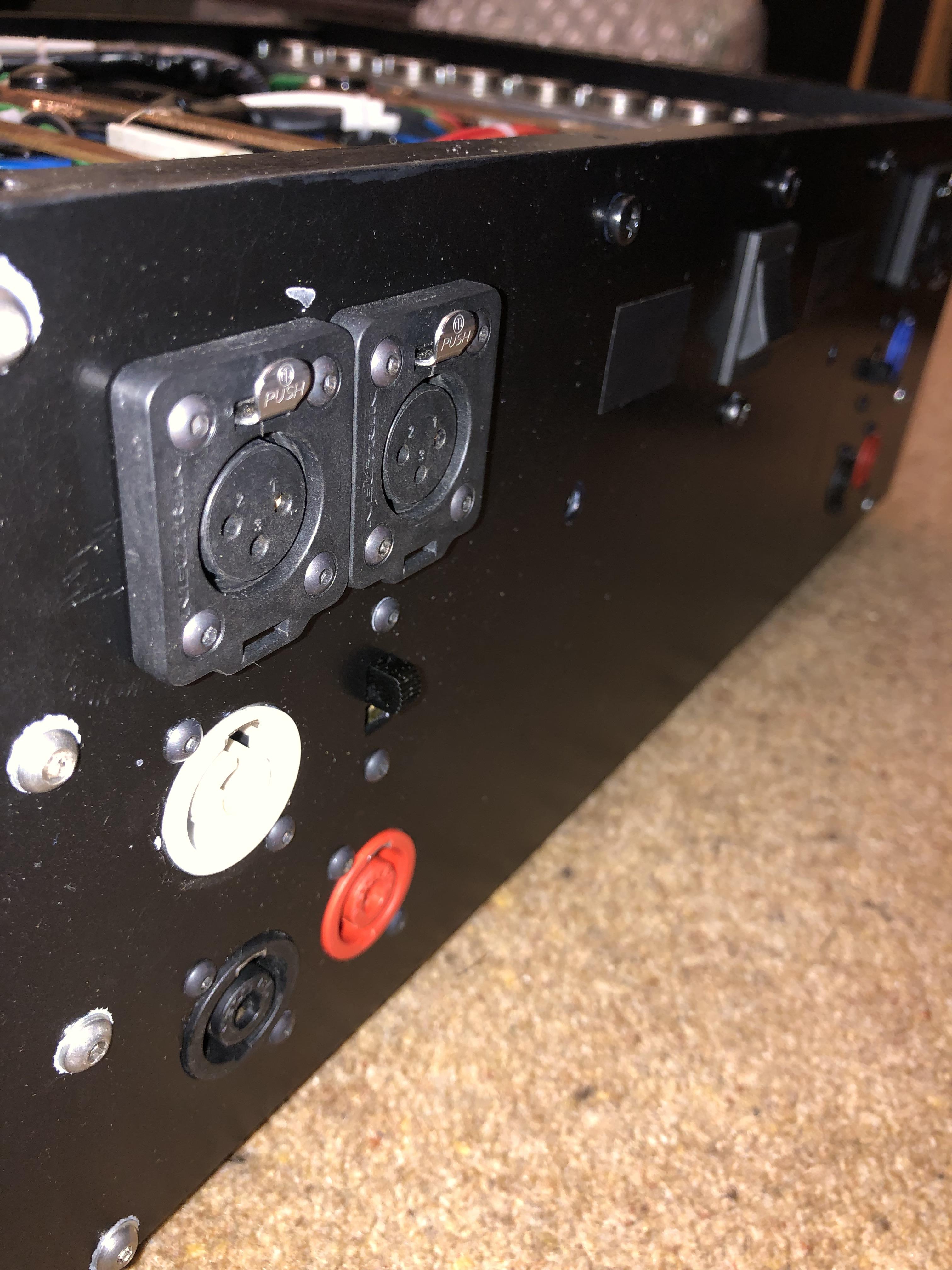
At least you know it works then...Alan, thank you for this link, I have wanted to read this excellent article before, but the previous searches/links have been dead. I will follow this and your advice and split the link between pin 1 and 3. Attach shield of the singal internal cable to pin 3 and attach pin 1 to chassis.
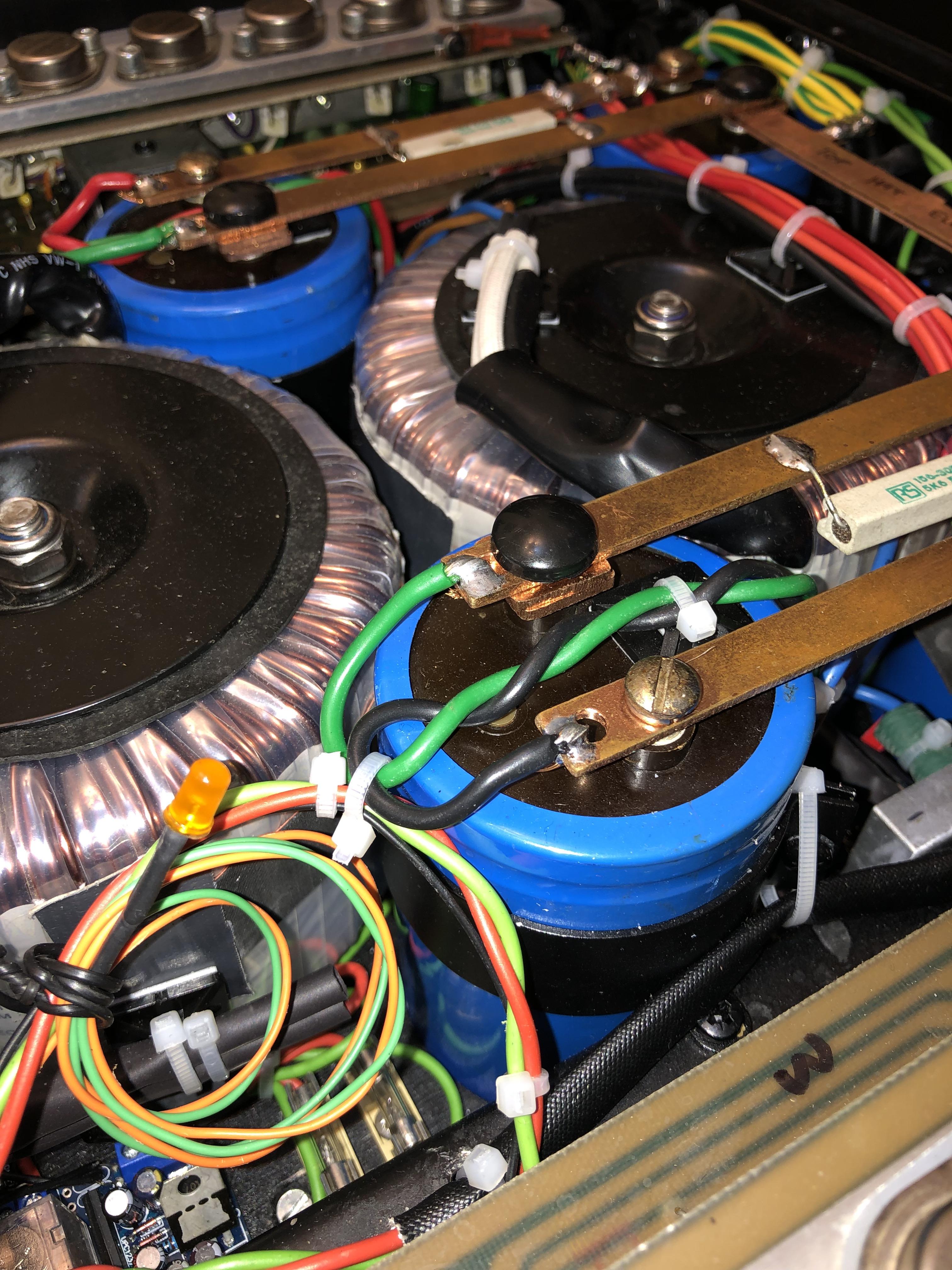
Please don't. It's a high power DC coupled circuit. This means that any imbalance between small transistor pairs translates to a much bigger offset at the output and potential tragedy. The offset pot is a fine adjustment and won't compensate for problems elsewhere. In addition, the design is stable using the specified transistors and there's no guarantee that it will still be so with alternatives. Messing about with big poweramp design needs know how and test equipment that's good enough to let you see what's going on at all frequencies and load conditions.and maybe some low noise newer versions of the small signal transistors (as common on quad 33 restorations)
sounds like a good find, the transistor selection reminds me of 70s-80s quad and many others.
no reason it won't sound good.
I'd be inclined to measure at least the frequency response, distortion and noise with some of the free software and a soundcard. I'd use RMAA in this case,
at least then you have a baseline of performance and you know there are no faults
there is a great article on PC measurement here, https://audioxpress.com/article/pra...ds-for-data-acquisition-in-audio-measurements
strangely the link to all parts is only on the first page.
probably the hard worked electrolytics would be first for replacement, and maybe some low noise newer versions of the small signal transistors (as common on quad 33 restorations)
make sure you know how to reset the DC point and Bias before changing transistors.
If it's going to be used to drive subs then I'd also leave the front end LPF filter unadjusted (ie retain teh 4k7 input resistor, and not drop it to 2k7 or 2k2 as suggested earlier in thread))
Yes that limits the top end to c 23khz as designed - but that's actually a good thing for noise and stability. And one less unchecked-change made before being sure the thing is working properly.
have left something floating when it needs to be connected to ground. Try reconnecting pins 1 and 3 and see if that improves anything.I will follow this and your advice and split the link between pin 1 and 3. Attach shield of the singal internal cable to pin 3 and attach pin 1 to chassis.
 This site says it'll take about 3 minutes to drain down to 10V