advertisement


DIY SMD PCB

john.luckins

pfm Member
I thought I would share my first Kicad SMD board design. It is also only my second Kicad board, the first being thru hole.

https://flic.kr/p/2kPhsa7

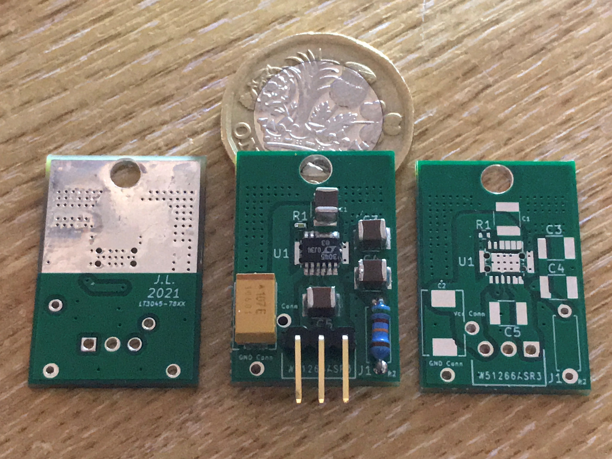
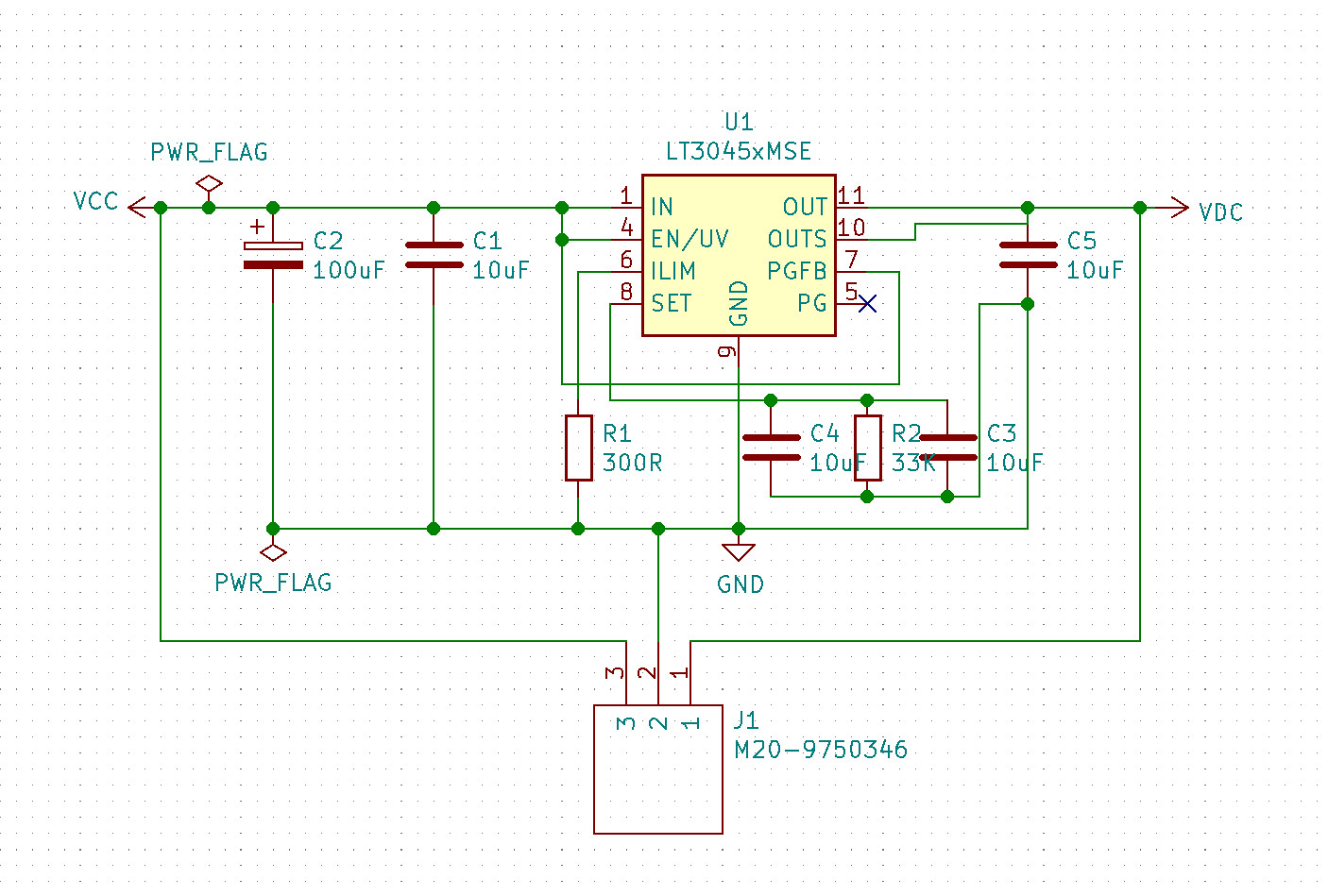
It is an adjustable LT3045 regulator with a 3 pin 78xx series pin out. It can source 500mA and I've just tested it with a heatsink dissipating 7.5 watts. It's output voltage is set by a hand soldered thru hole resistor and it has separate solder pads for 0v and Vin if you wanted to insert just its Ov and Vout pins in a circuit and run a separate supply feed to it, handy if you are modding kit with it. It has lower noise than the standard LT3045 circuit and uses higher voltage X7R capacitors as they hold their value better with voltage changes.

Now here's the interesting bit. It cost me only $1 extra to get 50 rather than 10 of these produced by PCBway, so I have more than I need. I also soldered the one in the photo in my kitchen oven this afternoon! It was much easier than I had expected, perhaps because of the leaded solder. The only special tool used was a £10 oven thermometer. Even the underside of the LT3045 soldered properly to the heatsink.

Over the next few weeks I'll be completing and checking some more of these and if things go well I'll test the water here for a group buy. I'm not trying to make money on these so we are looking at around £10-£12 fully populated (apart from the setting resistor). That's quite a saving on the ebay offerings of similar quality.

Maybe there will be no interest, but you never know....

John
 
That's great Fran, I'll try to do a batch of 10 this weekend I've just been testing the first one and it can comfortably dissipate 7.5W through an attached heatsink, and the 500mA current limit works well.

51074556232_bae9a85cd9_k.jpg
[/url]

51073775028_ed2d06ec9a_h.jpg
 
Nice one they look ace. Try measuring it dropping around 3v, they measure better at higher drop.
 
Thanks guys, an update, I also splashed out and bought a framed stencil for this board and it is brilliant, it'll make getting the right amount of solder paste on to the pads a doddle.

51074922307_deac88383d_k.jpg


I also noticed that the 3 pin header is too short and found some that are 6mm longer so you can get more board/component clearance if needed. I might just supply the pin headers for self soldering in case not everyone wants to use them. Just priced up the components and it is all just shy of £12.:)

I have to admit that I have wanted to design and build my own boards for an awfully long time now and it was just the mastering of the CAD package that was in the way. It has really opened up the floodgates. I now have more than a dozen circuits to lay out including two regulators, a single rail rectifier/smoothing board, a cap multiplier board (finished), two headphone amps and a power amp with integrated front end regulation. In the longer term I have plans for a 4 layer DAC board with integrated regulation. I plan to share as many of these as are wanted!

John
 
Very nice indeed, would be interested in a few.
How much did that stencil set you back, I don't remember them being cheap.
 
The stencil was £15. I made a mistake and ordered it in a frame so the shipping was steep as well. Would have been half that without the frame though as I'm finding now, the frame makes it even easier to keep it in place. As this was my first stab at all this I wanted to do it properly. I may yet build my own convection reflow oven...

John
 
Maybe even use a 3D printer setup to build a selective solder system for any through hole? Just for fun of course!

Steady on now!

When I said "build an oven" I only really meant modify a small Aldi or Lidl one with a fan and timer. The problem with a big kitchen oven is just that, way too big with too much thermal inertia. Mine takes a full 8 mins to get from 138 to 200 Celsius. Something the size of a small microwave would be better. Decent proper reflow ovens even that size cost more than a grand. This is still only supposed to be my pre-retirement hobby and has to stay under the wife's radar which is super sensitive.

BTW can 3D printed items really take 200 Celsius?;)
 
Looks good John, well done. I know you have been wanting to do this for a long while now. I'm impressed that you have bothered with the DIY soldering. I get all my parts done at the board fab house. Seeed do it so cheap it's almost free.
 
The diy solution for a solder oven is to use a toaster oven with a controller - I'm fairly sure there is an arduino sketch and hardware description out there if you google around. A friend has one and it works well, but you need to be careful about the solder paste, get any of it wrong and you'll get lots of tombstoning. TBH unless you're doing lots of these its probably quicker to do them by hand.
 
Its been a long time since I saw such mis-aligned holes like the GND THT hole, Chinese PCB fabs usually do a lot better than that
 
It's the whole board, not really a problem here but I know what you mean (although never really seen Chinese boards before).
 
When I moved company in 2015 I moved from getting prototype PCBs from aerospace approved PCB manufacturing and assembly in the UK, to commercial quality from China. The Chinese PCBs are better in every way except a few days extra to get to my desk. I am talking about very small quantity prototype runs, perhaps 10 or 20 off, and only slightly larger production runs, maybe 100s off, not mass manufacturing.
 
When I moved company in 2015 I moved from getting prototype PCBs from aerospace approved PCB manufacturing and assembly in the UK, to commercial quality from China. The Chinese PCBs are better in every way except a few days extra to get to my desk. I am talking about very small quantity prototype runs, perhaps 10 or 20 off, and only slightly larger production runs, maybe 100s off, not mass manufacturing.
Back in the 80s, UK made boards with what are now very coarse design rules had drilling breaking out of the pad all the time.
 
Thanks guys, an update, I also splashed out and bought a framed stencil for this board and it is brilliant, it'll make getting the right amount of solder paste on to the pads a doddle.

I also noticed that the 3 pin header is too short and found some that are 6mm longer so you can get more board/component clearance if needed. I might just supply the pin headers for self soldering in case not everyone wants to use them. Just priced up the components and it is all just shy of £12.:)

I have to admit that I have wanted to design and build my own boards for an awfully long time now and it was just the mastering of the CAD package that was in the way. It has really opened up the floodgates. I now have more than a dozen circuits to lay out including two regulators, a single rail rectifier/smoothing board, a cap multiplier board (finished), two headphone amps and a power amp with integrated front end regulation. In the longer term I have plans for a 4 layer DAC board with integrated regulation. I plan to share as many of these as are wanted!

John
This sounds like an ideal regulator for the Raspberry Pi/HiFiBerry DAC I want to build - is it too late to go on the order-list?

BugBear


advertisement


Back
Top