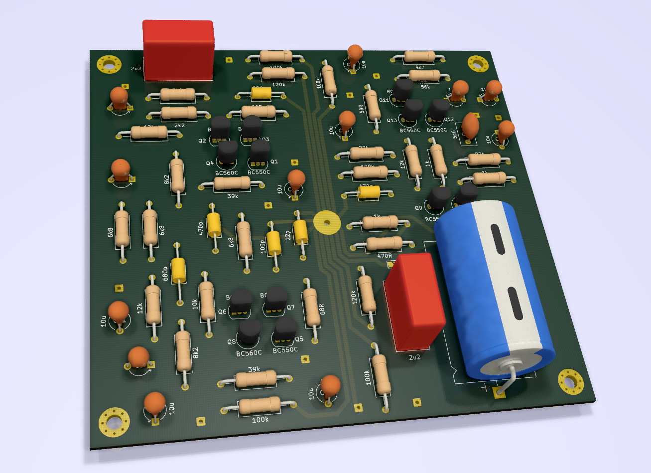
As promised I tried to reconstruct the starfish circuit and open a new starfish thread. I used the guide-PDF and BOM v1.2, but I don't have full schematics of the starfish, and I am not a circuit designer, so there might be mistakes in the following diagrams. First the audio circuit, a standard Naim style 729 (TA, time aligned buffer) and 321 (gain stage) powered symmetrically from multiple sources:
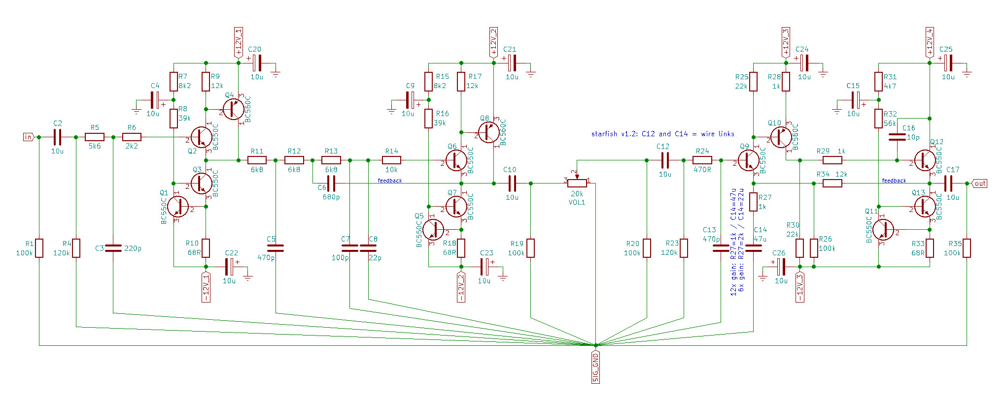
I am not sure if all these these parts should return to the signal ground or if it's better to pull some of them to the noisier power ground (and connect them at one point together). The starfish BOM says C12 and C14 shall not be populated but shorted with wire links: what happens in that case to R20 and R23? BTW I used "starfish minus 100" as part references in this diagram (i.e. C12 is C112 on the starfish schematic).
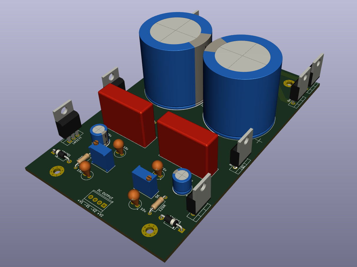
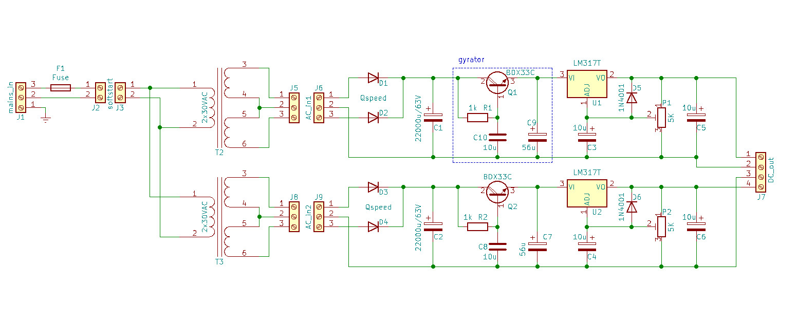
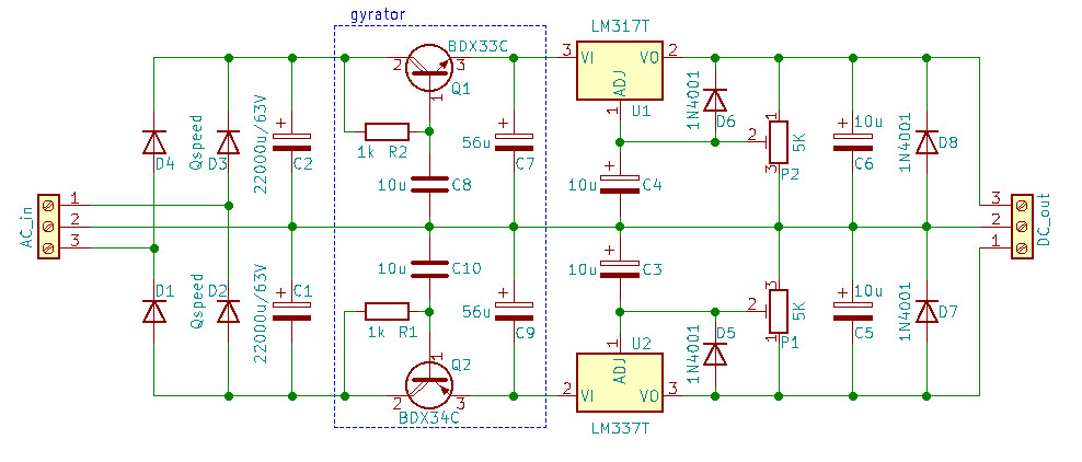
I ditched the Traco DC-DC which was originally part of the starfish and instead start with a simple hicap style PSU with 2 separate rails to feed the negative and posive supplies of the audio circuit:
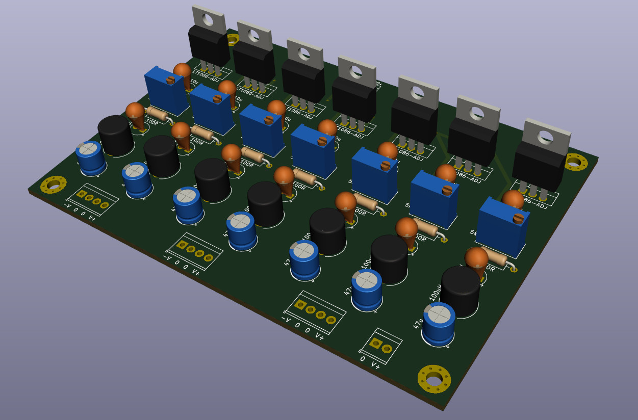
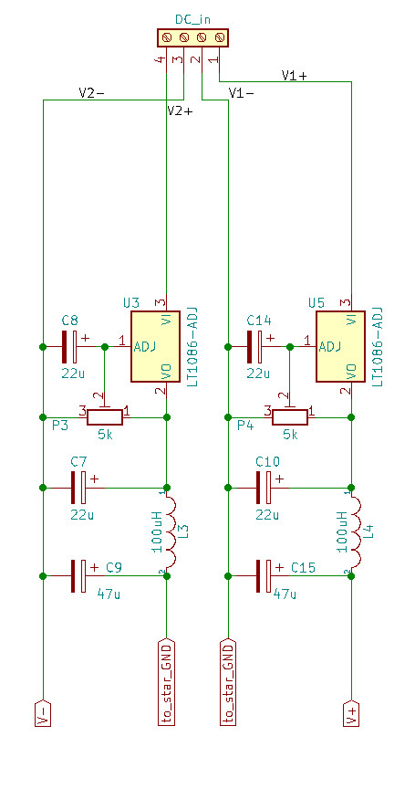
The original starfish used 1086s as local regulators, I draw them for negativ und positive rails:
Or are 1763s better...? The solder jumpers are there in case fixed voltage regulators are used:
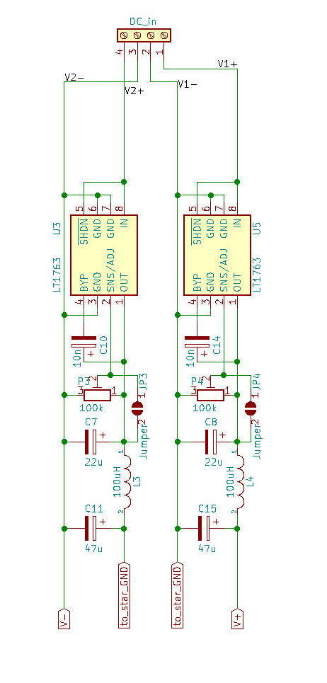
The grounds can be routed to one star point in the preamp case if PSUs are done this way. A simpler solution would be to omit the local regulators and use only one stage of regulation in the PSU case:
The audio circuits needs 4 positive and 3 negative supplies per channel, so one would have to duplicate the shown regulator circuits. Or use advanced solutions such as TeddyRegs, SuperTeddyRegs or ALWSRs etc.
Questions:
- where can I order good quality PCBs from gerber files for audio circuits? I work on kicad and live in Europe.
- if replacing the volume pot with a stepped attenuator: could the DC coupling be reduced as suggested in this thread?
- should we consider to replace the TA stage with something like a B4 or a Kuartlotron?
- should we consider to just ditch the TA stage as shown in the air guitariste schematic?
- what about the current source mod for the gain stage as suggested in this post?
- what about the current source mod for the TA stage as suggested in this thread?
[questions edited]
I am not sure if all these these parts should return to the signal ground or if it's better to pull some of them to the noisier power ground (and connect them at one point together). The starfish BOM says C12 and C14 shall not be populated but shorted with wire links: what happens in that case to R20 and R23? BTW I used "starfish minus 100" as part references in this diagram (i.e. C12 is C112 on the starfish schematic).
I ditched the Traco DC-DC which was originally part of the starfish and instead start with a simple hicap style PSU with 2 separate rails to feed the negative and posive supplies of the audio circuit:
The original starfish used 1086s as local regulators, I draw them for negativ und positive rails:
Or are 1763s better...? The solder jumpers are there in case fixed voltage regulators are used:
The grounds can be routed to one star point in the preamp case if PSUs are done this way. A simpler solution would be to omit the local regulators and use only one stage of regulation in the PSU case:
The audio circuits needs 4 positive and 3 negative supplies per channel, so one would have to duplicate the shown regulator circuits. Or use advanced solutions such as TeddyRegs, SuperTeddyRegs or ALWSRs etc.
Questions:
- where can I order good quality PCBs from gerber files for audio circuits? I work on kicad and live in Europe.
- if replacing the volume pot with a stepped attenuator: could the DC coupling be reduced as suggested in this thread?
- should we consider to replace the TA stage with something like a B4 or a Kuartlotron?
- should we consider to just ditch the TA stage as shown in the air guitariste schematic?
- what about the current source mod for the gain stage as suggested in this post?
- what about the current source mod for the TA stage as suggested in this thread?
[questions edited]
Last edited: