advertisement


Bias voltage issues in my DIY build based on reused NAP boards

Jon Dennis

Bo Nydal
Hi all,

I'm a relative novice building an amp based on a couple of NAP boards that were taken out of my NAP250 when it was Avondaled earlier this year. I have [I guess rather optimistically] tried to reuse them without renewing any parts and that is probably somewhere between partially and totally responsible for my bias setting issues. I also have a pair of NAP140 boards, also taken out of an Avondaled amp, that I could deploy instead if needed.

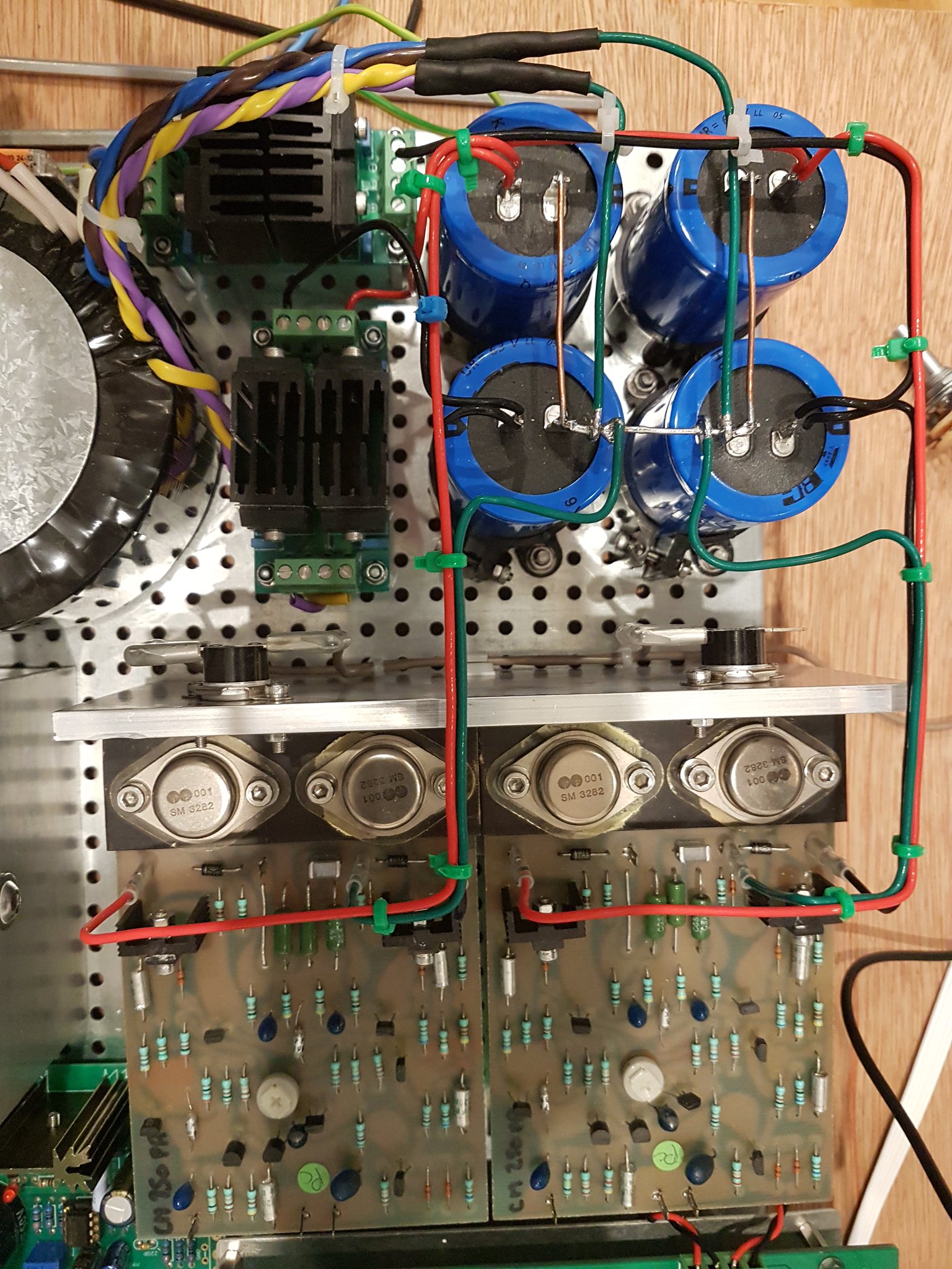
My setup is a Toroidy traffo with 4x30VAC(nominal) secondaries arranged as two 30-0-30 secondaries. These feed a pair of Schottky bridge rectifiers which, in turn, feed two pairs of 10000uF/63V Vishay caps. The raw DC from this is fed to the boards. In practice the voltage supplied by this arrangement is +/- approx 43.6V.

On first fire-up all was calm; no blue smoke or bulging caps so I thought I'd have a go at setting the bias. Measuring the voltage across the 0R22 resistor (R12 in the acoustica.org.uk instructions I was following) gave me a reading of about 1.9mV at minimum and about 2.1mV at maximum when twiddling the trimmer on one of the boards and a range of 1.4mV to 1.8mV on the other. Needless to say, not what I was hoping for.

My first thought was that the trimmers might be knackered and need replacing but I am guessing that, in fact, there's probably a whole galaxy of possible reasons for the outcome observed and hence this request for advice and assistance.

I would be very grateful for any advice on possible reasons for the very low bias voltage levels, and what I could do to remediate them. Also advice on the servicing actions that I should have applied to the boards before attempting reuse them would be very welcome as would suggestions for lowish cost improvements I could make to them over and above the minimum servicing.

Here is a picture of what I have (if the upload works):
50092875528_c9e1a737aa_k.jpg


Thank you for reading the post.

Bo
 
Hi A couple of things. Firstly +-43 volts is pretty high. I don't know what the limit is but I would say you're pushing it there. Someone with more knowledge should be able to advise you on that. I think the 250 runs at about +-40v and a 180 at +-38v.
Secondly, you've only attached one 0v line and that's the one to the output zobel. The first two current sources are referenced using the other 0v point so the both the long tailed pair and the voltage amplifier will be turned off. Speculatively, if the 43v is over the limits then that might have saved you.
The input should probably be grounded as well when you do the bias measurements.

Hi Dave, thanks for taking the trouble to reply.

I've read more than once that the NAP boards are able to take a supply up towards +/-50V but based on your comment I'll certainly hold off any further testing until I can confirm whether or not my supply level is likely to kill the boards.

The 0V point on the input side of the board has been a source of considerable uncertainty for me, I must admit, and I wasn't aware that it constituted a vital reference point. On the basis that my NAP140 boards don't even have that connector I wasn't sure whether to ground it to the 'star' ground or to the 0V on the preamp (which is implied by the NAP140 arrangement) or to just leave it unconnected. The latter was my default, with experimentation in the event of noise or silence ! When I resume testing I shall connect it to my 'star' ground per your advice.

When you say the input should be grounded when I do the bias measurement, I'm not completely sure what you mean. The input ground tag is already connected to the input side 0V tag by the pcb trace; are you saying that I should connect the input signal tag to the 0V tag as well ?

Thanks, again, for helping.

Cheers,
Bo
 
+/- 43.6V is probably OK. I've run NAPA boards at +/-50V but changed some of the front-end transistors to higher voltage types just to be sure.

Bias should be set with no load/speakers connected to the output and no signal input. As Dave pointed out, it is essential to have 0V connections back to the smoothing capacitors from both the front and rear edges of the board. It is preferable to measure the bias across both output emitter resistors in series as this is more accurate than using just one of the two. Bias should be set to 7.2 mV across the two resistors with the amplifier cold.

https://photos.google.com/photo/AF1QipMztH4FFbLlnRmNyN3Fs4bB0amG9tkhlSjru1GR
Hi, thanks a lot for responding. Loud and clear on the 0V connections; it's nice to put my mind at ease regarding that conundrum tbh. I've also been somewhat discomfited by the wide availability of apparently conflicting info on the biasing procedure so I'm very happy to have your advice on that as well.

The 'probably', in relation to the rail voltages, is slightly unnerving... can I ask some follow up questions ?
1. How would 'not ok' likely be apparent; silence, flash/bang, smoke, discrete component failure, widespread component destruction ? I suppose, what I'm asking is how big a problem am I courting ?
2. Would the 'not ok' condition be likely to manifest in the first few minutes and hours, might it be brought on by pushing the amp harder or might it happen at any time, for no obvious reason ?
3. Is there any simple way to drop the rail voltage without a regulator and without generating excessive amounts of extra heat ? I realise that this is probably the equivalent of asking for a magic wand, but I had to ask.
4. Do you have details of the transistor changes I would need to make to take the over voltage risk away ?

Thanks again for your advice.

Cheers,
Bo
 
1/2. I inserted the 'probably' to protect myself! I can't see anything really destructive happening with the voltage rails you have.
3. There's no easy way and no point of doing it anyway.
4. See post #20 on page 1 of this thread: https://pinkfishmedia.net/forum/threads/bias-napa-board.180391/

I'd also recommend replacing all the tantalum bead capacitors on a like for like basis using good quality components.

Thanks a lot, I really appreciate it.

Cheers,
Bo
 
Hi Bo I've just noticed the 0R22 output resistors have been replaced with wire links. This won't do much for the stability of the amp when you connect a speaker up. I would definitely replace them.

And it looks like I was being too cautious with the supply rail voltages.

Cheers and good luck
 
Hi Bo I've just noticed the 0R22 output resistors have been replaced with wire links. This won't do much for the stability of the amp when you connect a speaker up. I would definitely replace them.

And it looks like I was being too cautious with the supply rail voltages.

Cheers and good luck
Hi Dave, thanks for that. On the advice of some of the good gentlemen of this parish I have replaced the 0R22s with links because I shall be connecting the speakers via a damped inductor, so as to free the amp from the tyranny of NACA5 :)
Cheers,
Jon
 
Why don’t you put the inductor/ resistor where the link is?
Hi, thanks for that. I could do that, I suppose, but it's quite large and wouldn't fit horizontally so I'd have to have it sticking up in the air somehow. Difficulties aside, I am now thinking that I really should find a way to make that work. Thank you for inducing me to challenge myself to find a better solution.
Cheers,
Bo
 
There looks to be a ton of room there Jon so I'm sure you'd get them in. The coil/resistor combination is roughly 25mm long. When you wind the coil leave the legs a bit longer so you can bend them to fit if you need to. It doesn't matter if they sit a bit higher up off the board.


advertisement


Back
Top