advertisement


A&R MC60 Moving Coil Pre-Amp (KiCAD)

graham-r

pfm Member
OK, so this is as a direct result of being stuck at home with too much time on my hands.....

For the past few weeks I have been teaching myself to use KiCAD (I might be needing this for work....), so I chose a couple of subjects and started converting schematics into actual PCB designs (i.e. Gerbers).

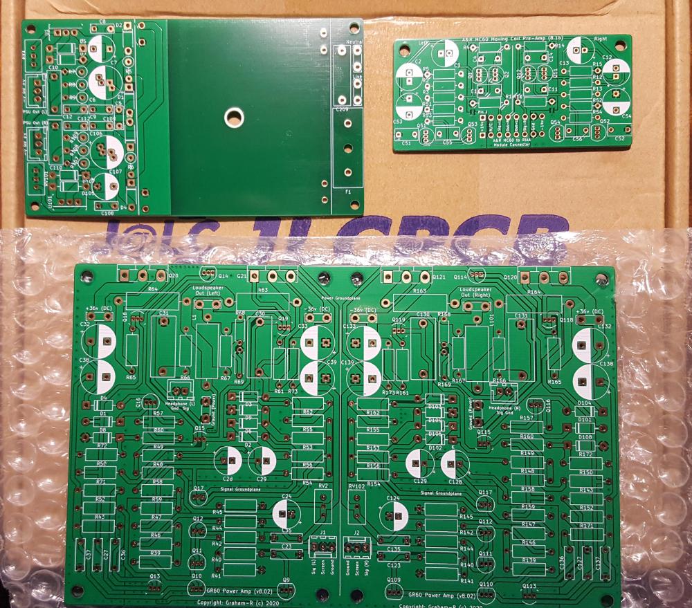
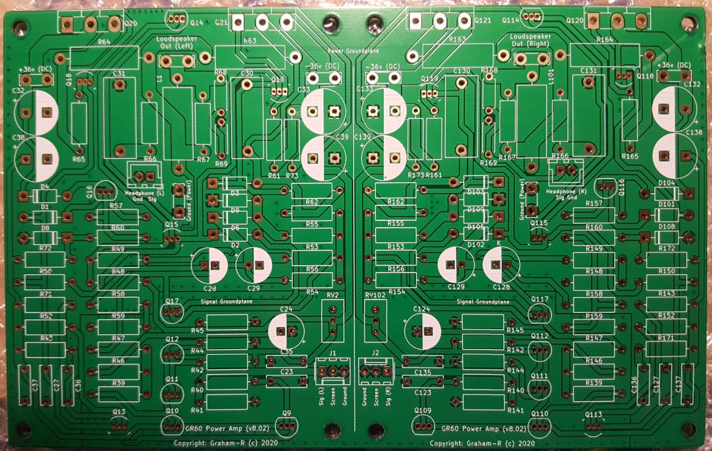
These included some Jaguar car reversing camera RGB interfaces, and the A&R A60, the latter was so I could eventually make a 4 channel car audio system for a car, and perhaps also a 'clone' A&R A60. I have completed various Power Amp version, the pre-amp/tone controls and the RIAA module. I haven't yet got around to ordering any PCB's for these yet - I am loathe to use the Chinese fabs after recent events.

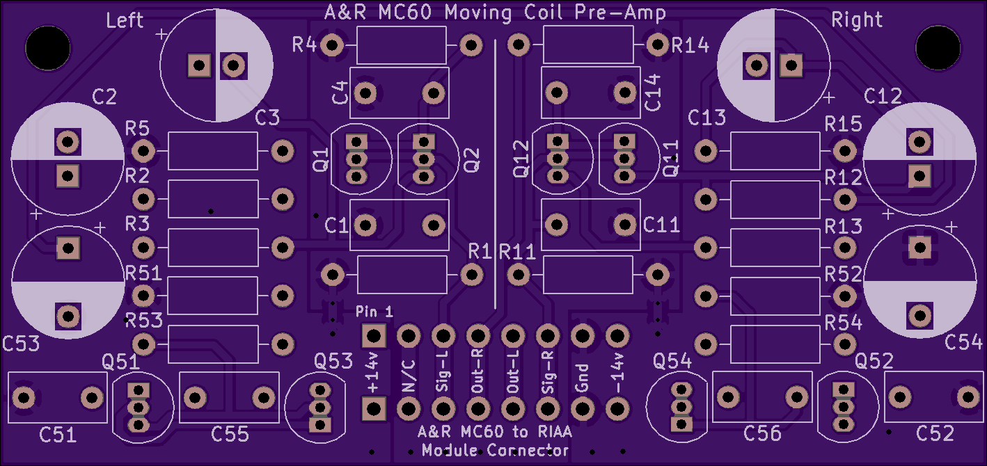
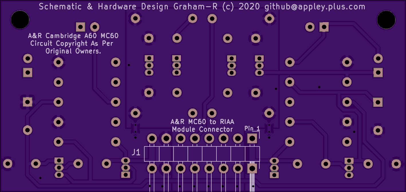
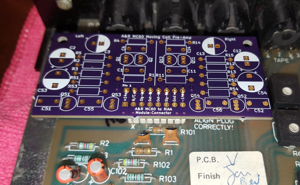
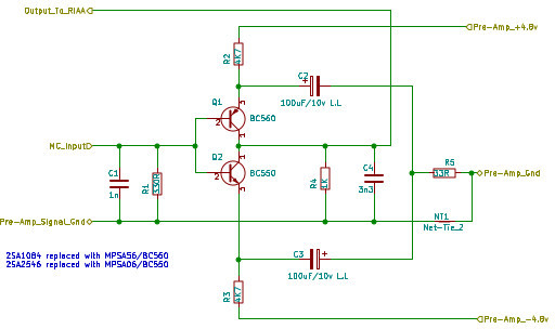
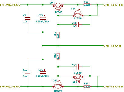
This thread is concerned with the MC60 moving coil module, I don't have one of these and when they do come up for sale they are stupidly expensive considering what they are (simple).

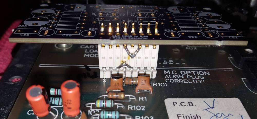
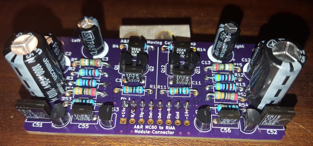
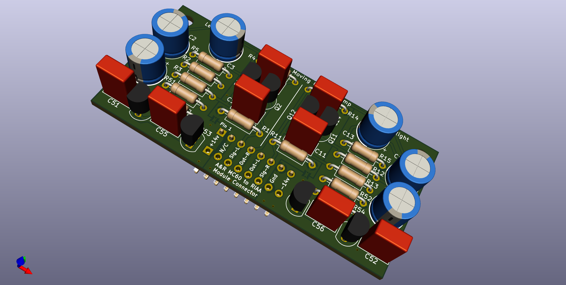
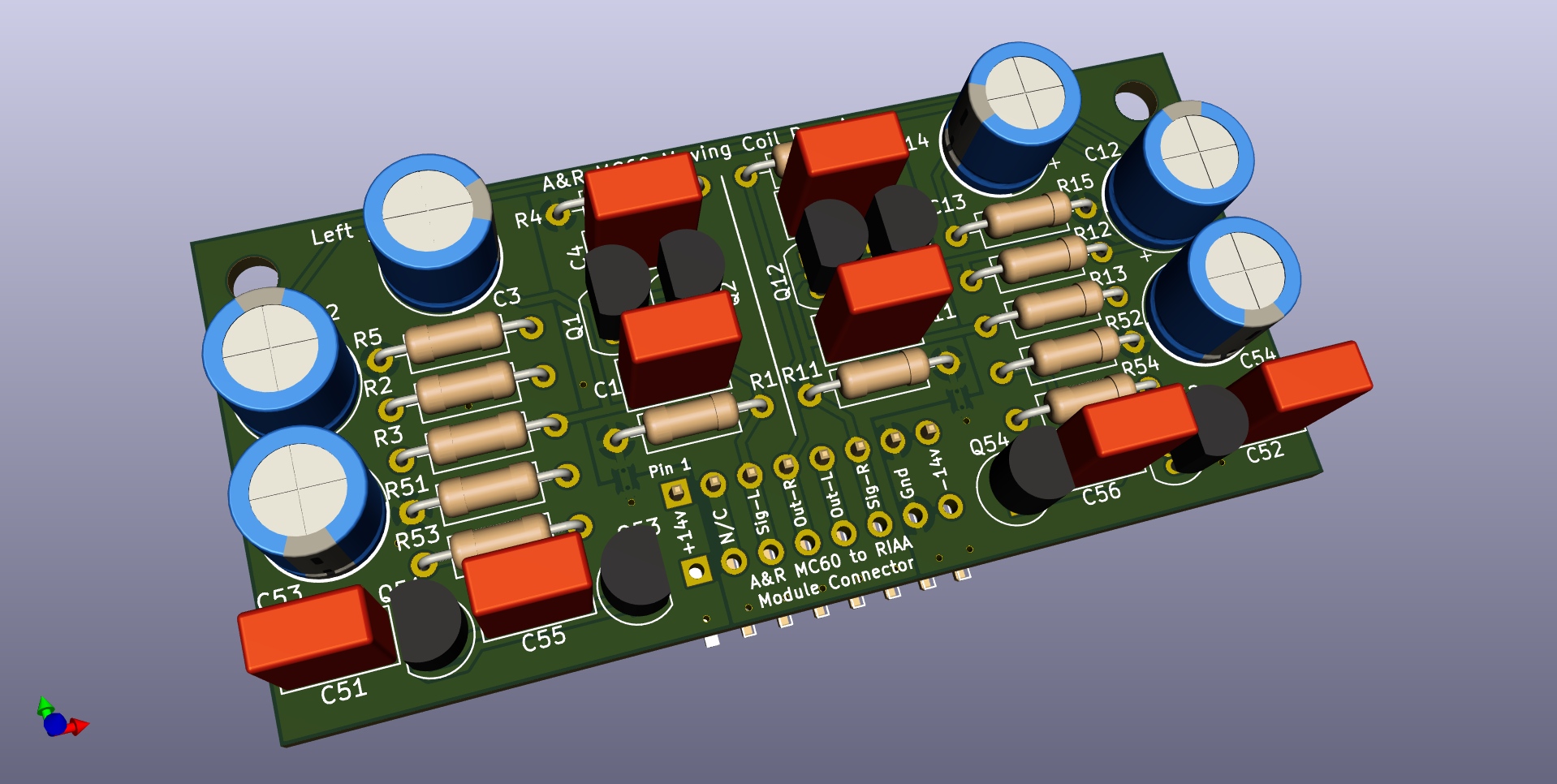
So I knocked one up myself, which is identical apart from two changes - I am using different transistors in the amp stage and the connector seems to be an obscure (French ?) thing called a 'Pressac'.

For the latter I decided to use a standard pin socket to replace the existing PCB mounted connector and either a straight or 90 degree pin header (think Raspberry Pi), these can be updated at a later date.

Anyway if this works I may well design an updated version with at least a better PSU.

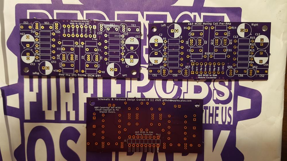
I have just ordered 3 PCB's from OSHPark which are likely to take several weeks to arrive so until then not much more to say, apart from uploading a schematic.

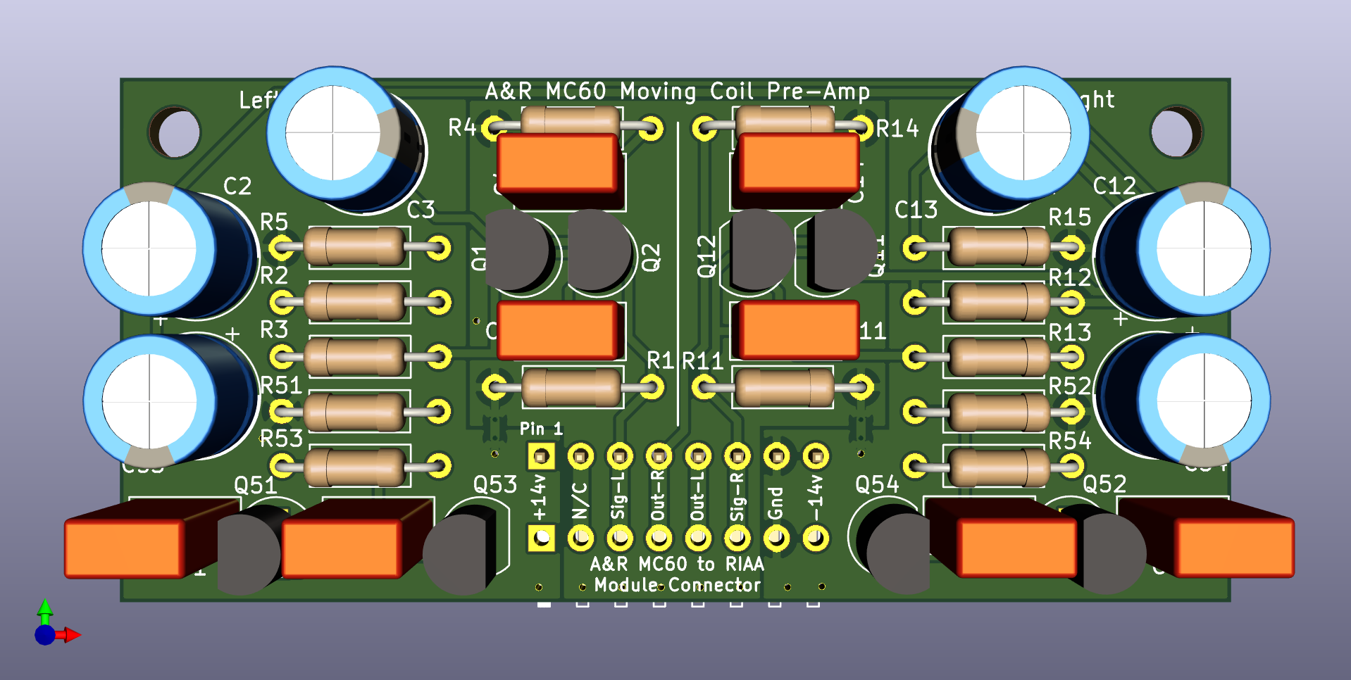
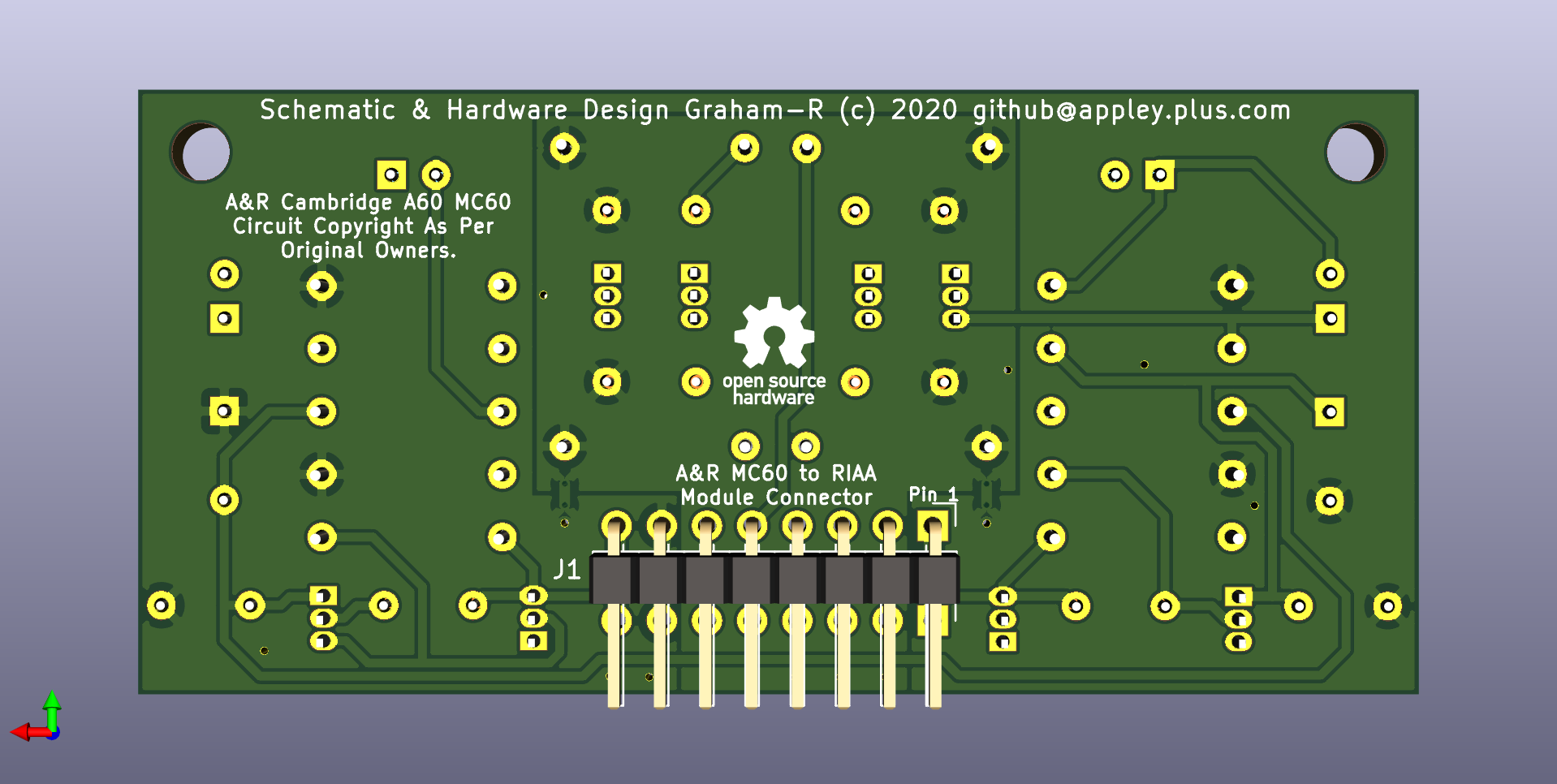
Here are some pics of how it should appear when built.

8WpIYQI.png


8FJ0fsI.png


YPzCGyx.png


eJpDWRF.png
 
Last edited:
Nice work!:)

I presume you've used suitably low noise for MC app transistors if you used different ones?
I haven't actually done a proper BOM yet, I was just interested in the pin spacing/component diameter etc, actually this PCB was just intended as a design example in that I intended to design my own version and make that.

What changed is that the PCB's are quite small (74x36mm) and therefore not expensive ($20 inc P&P from the US), with components they should be about £10 each, which is a bit better than the £129 that an original MC60 sold for. And they will be purple.......

The original transistors are 2SA1084 (pnp) and 2SC2546 (npn) - both have same pinouts (looking at the flat) ECB - i.e. Japan style.

BC550/BC560 (CBE)
MPSA06/MPSA56 (EBC)

I went with UK/US style pinouts with the base on the middle pin so both styles could be used, I used the BC as a model for the layout, if the MPSA* are used they will be rotated compared to the silk screen on the PCB. The original 2S* are probably still available and could also be fitted but it would be tricky.

Any suggestions for components gratefully received - currently I am looking at
EVOX_CMK and Nichicon Audio Grade Electrolytic Capacitors.
 
I have just cancelled the order and remade it - with a revised PCB design that was just a little smaller to make sure it fitted in the A60 with a bit more clearance, I also updated both ground planes a bit.

As it is now 72x34mm I saved myself a whole US Dollar in the process, which is nice.
 
The boards should be here sometime after 20th May according to OSHPark (a lot of purple going on there).

Better start sorting out the BOM properly

This is from an email

2.84 x 1.34 inch (72.1 x 34.1 mm) 2 layer board. The panel your boards are assigned to has been sent to the fab. We'll let you know as soon as they're back.

3 boards at $19.00 per batch of three $19.00

nwzmUXM.png


eYoHuF9.png
 
The newly minted PCB's are on their way so I should be able to get on with this very soon.

I shall probably take the opportunity to refresh my A60 with some new electrolytics and trimpots, a few poly caps in critical places, and a Blue ALPS.
 
PCB's are still in transit...... as far as I can tell they haven't even left the US.

I really want to get on with this........
 
They have finally arrived - they took so long arriving that I have moved onto other things, so they will have to wait until the w/e

In fact because they took so long to arrive (they sat in an LA warehouse for over 7 weeks without moving !) that I sent a slightly modified version to JLCPCB just to see what their quality/delivery was like. This was just about 10 days ago - and they nearly beat the OSHPark on delivery as they should be here in a day or two !
(This means I now have approx 6 spares if anyone is interested - assuming they work that is....)

I might use OSHPark again - but I probably won't be using Chinese fabs again if I can help it - there are a few UK fabs that look interesting if quite a lot more expensive.

They are very nicely made however - here's a pic for anyone who is interested.

WrpJF0E.jpg
 
The 2SA1084 etc devices were remarkable, and I have never found an adequate replacement. They have very high hfe (so current noise is low) and running 5mA in them can get you down to about 0.5nV/rt Hz, and they have a very low 1/f noise corner. A few devices can get comparable white noise performance, but I have never seen anything as good at low frequencies.

Now you can argue that low frequency noise is not very audible, and the A weighting curve reflects this. However, in an RIAA application, you have masses of bass boost, which eats up the audibility weighting, so 1/f noise does matter.
 
Thanks for the info - interesting - a good place to start by matching characteristics of alternative devices, even though this can't guarantee anything really. The 2SA1084/2SC2546 devices are usually described as 'general purpose', imagine how good they would have been if they were designed specifically for the task - all the same they do offer a "useful combination of low-noise, wide bandwidth, high gain, and good linearity" - a quote from St Andrews uni !

The 2SA1084/2SC2546 devices are still available on ebay/etc (!) as original etc - which probably means they are just some old generic transistor labelled as whatever they want, call me cynical if you like..... but the chances of them being genuine are not good.

So it does make sense to use modern devices that are 'good enough' (whatever that really means) as they are freely available and <should> be genuine, also I am not equipped to measure noise levels at the precision required it makes sense not to fret over it - does it sound good shall be the mantra.

I am going to start with what I have to hand (BC550/BC560) as these will work and I can at least test the PCB out. Other devices may well be better - there are many excellent MC/RIAA amps out there that measure very well - perhaps substituting the BC550/60 for the devices used in those may be an option.

What may have an equal or bigger effect on performance are the quality of the other components, the differences in the PCB layout - it is now largely laid out symmetrically with power supply components on a different ground plane to the signal components (admittedly this is going to have a minimal effect), and the PCB has top and bottom grounding planes which should also help.

Time will tell, if it sounds good then I shall be happy.

PS. I also designed some compact stereo A60 power amp PCB's - as the next little project, these should also be here from JLCPCB soon.
 
Last edited:
BC550 / 560 are a reasonable choice. They have decent Hfe and low capacitance, so should substitute without needing circuit changes. From experience, noise will be high enough to be annoying on a low output MC, like say Ortofon, but ignoreable on something like AT OC-9 or Koetsu Black.

ZTX650 has low white noise, but much higher capacitance (30pF vs 6pF) and lower gain (150 vs 600) so it is not obvious that they will work in the circuit without checking with a Spice simulation, and maybe tweaking feedback, compensation or bias points.

The Hitachi devices were made by an epi process, which probably explains a lot of their performance. Conventional PNP starts with a P doped wafer. N dopant is then diffused in, to balance out the P and leave a net excess of N. This makes the base. The emitter is made by an even higher concentration of P dopant being diffused in a shorter distance. The net effect is the base is counter doped (rasing its resistivity), and has blurry boundaries. Epi devices can be made with pure doping in each layer, and sharp boundaries. This allows a much lower resistivity in the base layer, allowing a thin base to be used (for high gain) without rbb getting high.

Nobody but Hitachi (later Renesas) bothered running a process like that.
 
Where did you learn about this 'EPI' process, never heard of it - sounds an expensive process though.

The original reason for doing this (learn KiCAD, make PCB etc) has been realised, the next stage is to prove that I can get it to work on the A60 PCB - the standard connector on the A60 PCB is a bit weird and I haven't been able to find anything even slightly close so it may have to come out completely - not a simple task.

Assuming it all works using the BC550/60 then I may well seek out some 'better' transistors and see if they make a worthwhile/noticeable difference.

You are also right about the output level of the MC cartridge having an effect on the audible noise floor - certainly my Audio Technica cartridges will be fine, but I am also looking at something a little more esoteric as they are old enough to be passed their best.

But, unfortunately this weekend has become fully booked so I won't have much time to play (SWMBO has decreed etc), so in the meantime another picture.

JLCPCB's efforts.

asbpNsh.jpg


UOxChwa.jpg
 
Made a little progress on this - hopefully this weekend I shall be able to make a 'basic' version - using standard components found
in my parts box.

I have discovered that the PCB can be fitted to the strange Pressac A60 PCB pinheader connector without much problem - the trick is that a standard PCB pinheader pin will fit in the shorting plug along with the A60 PCB mounted pins, and it gives a really firm connection,

I will do this for now and maybe permanently as it removes the need to strip the amp down to remove the entire PCB to change the connector - see the second picture.

OX1rO09.jpg


P0sumJd.jpg
 
Last edited:
Ready to fit to the amp and test the newly populated PCB, I am going to try a direct comparison with a Trichord Dino stage into the aux input.

038k6IC.jpg


There are a few minor deviations from the standard circuit which will be sorted soon. The smaller electrolytic caps are just standard and ideally should (will) be replaced with those designed for audio use - when I do my next RadioSpares order. I've also used ceramic (X7R) caps on this one - apparently these are the worst for audio ! might be interesting to see if their is any appreciable audible difference after replacing them with film caps.

The MC60 is a very simple circuit being single stage (one channel shown below) and a stabilised PSU

6QgrHvM.jpg


PSU.
9tpfFkY.jpg
 
If you can match the BC550 and BC560 for gain at the operating point (about 1ma), the bias currents will cancel. If not, there will be a small DC current flowing back in to the cartridge. I don't feel that is a big deal, but some people worry about it.

The other point to make is that this is an odd circuit, as the gain transistors operate with almost no Vcb, so won't have a lot of gain. This is because the bases and the collector's are tied together. The PSRR is pretty limited, which is why it needs the regulated supply.
 
That is a very insightful post - got me thinking now......

I have matched the BC550CG/560CG almost exactly - took a while but I found 4 transistors that had a very similar hfe value (about 575 +/- 2 at an Ib of 4.6mA) - according to my little Atlas DCAS55 semi conductor tester. That is the best I can do with the limited resources I have (especially time).

The A&R circuit diagram show the input test voltages at the input and output (C-E junction of both BJT's) to be zero - so I shall do some more rigorous testing before I actually plug it into the A60 for the first time (hopefully later this week).


advertisement


Back
Top