advertisement


Townshend Merlin Help

colasblue

pfm Member
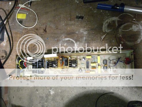
A friend of mine has one of these which has conked out.

I'm having a look at it and conceptually it looks quite similar to a valhalla but clearly isn't the same.

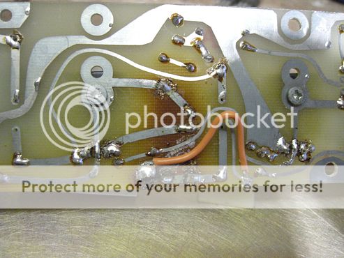
The obvious fault was that a large wirewound resistor had cooked itself off the board and disconnected from the track to the next component.

Easy fix I hoped but unfortunately not so much. I remade the connection and the resistor heated up nicely but no joy with the unit as a whole.

It looks like it's trying to work since about 80V ac appears at the output if it's switched to 33 or 45 and goes to zero if in the "off" position but it doesn't seem to have enough grunt to turn the motor. I get a bit of vibration on either setting but no rotation, and giving it a push doesn't help.

Also a 100V dc offset appears at the output on power up and then drops away quite quickly. On that basis I'm guessing some of its caps might be shot.

Anybody got a schematic or know anything helpful about them?

It has very few active components so if all else fails it's worth having a go at replacing all of them, but on the basis of what it's currently doing I think the digital side might well be working properly so it's likely a fault with the output section. I've already tried swapipng out the output transistors to no avail, mostly because I had some suitable ones in my bit box.
 
Photos would help
Does this unit have two outputs or just one to a phase shift network? Measuring both winding voltages and the voltage between two outputs allows calculation of the phase between them, should be about 90 degrees
 
Single phase.

The motor phasing is done outside the unit by using the tt 's normal 110V supply option.

I'll try to sort out pics just as soon as I've bought some batteries for the camera!
 
Right, got pics

The main problem seems be with the two big wirewound resistors.

I lifted the smaller one off the board about 10 years ago but the bigger one has now cooked the track off the PCB and disconnected itself.

34637ad4-5222-4058-86ca-1670af1d8e64-original.jpg


https://hosting.photobucket.com/ima...riginal.jpg?width=1920&height=1080&fit=bounds


I've repaired it (I think) but I'd really like confirmation that the two wirewound resistors actually aren't supposed to connect together at their closest point. I'm pretty sure they're not but if anybody has a Merlin they can look at confirmation would be good.

9a5de343-c65a-4d5d-aa4f-cbdb4448a7d9-original.jpg


https://hosting.photobucket.com/ima...riginal.jpg?width=1920&height=1080&fit=bounds


The other issue (which I'm hoping is a non issue) is that the m706b1 chip seems to be long obsolete so is there a drop in replacement if I need one?

19945e0b-5749-4913-97ad-f233fcea18fb-original.jpg


https://hosting.photobucket.com/ima...riginal.jpg?width=1920&height=1080&fit=bounds

PS can people tell me if the pics and links work properly since they've just changed photobucket and the new site seems to me to be an even bigger PoS than its predecessor
 
Is that an electrolytic next to the burnt resistor? There is no way it will be healthy after being cooked.
 
indeed it is and the output couples through it.

I've ordered a complete set of replacement lytics since the thing is getting on for 35 years old but those two axial 4.7uF caps are definite suspects.

The issue with that theory is that it was working OK until very recently so I'm not confident that there isn't something else a bit more fundamental amiss. It would be a strange coincidence if a gradual deterioration has suddenly become the secondary failure mode.
 
Woohoo it's working now. Not bad for a bit of guesswork without a schematic! Pretty sure one or both of the 4.7uF caps was the second issue.
 
Can you heatsink those big resistors at all or heat-shield the caps? Nice repair, I like the touch of snaking the wire to match the track!
 
The "snaking" is actually practical rather than artistic since it ensures the wire's insulation doesn't come into contact with the track running across the bottom of the board in the same direction which terminates hot running wirewounds. Hence meltdown related shortcircuit issue avoided at outset!

I think lifting that resistor off the board helps a bit as heat rises and it's now above the new cap. Obviously I've replaced the one that had "shed its skin" and with a slightly higher wattage to avoid a repeat performance.

The original caps have lasted 35 years so I'm not overly bothered about making additional improvements to extend their life further.
 
Max Townshend is very approachable in my experience and I visited him twice. Although Townshend Audio stopped selling turntables, he might answer your query. Perhaps he didn't design this circuit himself, but maybe he did. Max's phone number at the factory: 020 8979 3787
 
Woohoo it's working now. Not bad for a bit of guesswork without a schematic! Pretty sure one or both of the 4.7uF caps was the second issue.
I seem to have exactly the same problem.

Since I added the Merlin last year it had been fine but I noticed recently it was a little sluggish getting going at 33 although it would maintain speed when it got up there. However it would not get going at all on 45 from a standstill, or even maintain speed with a push. Don't think I have any problems with the track lifting though.

I have replaced the 4.7uf axial electrolytics and the larger ones at the input (mine were 33uf different to yours) but I’m still getting low motor torque. Did you replace the four very small electrolytics too?

Since I replaced those 4 larger electrolytics it will now maintain the speed at 33 and 45 but only if you give the platter a good push. I also notice the green LED in the power switch is flickering. Motor isn't getting enough juice to turn the platter from a standstill basically.

Can you remember what wattage you used for the wire wound resistors?

I think I need an 18k 5% but not sure of the wattage. The smaller one is a 4.7k 5% ‘W21’ type which I think is a 3W but not entirely sure.

Grateful for any help!

 
I actually replaced all the electrolytic caps for good measure including the two reservoir caps.

I only actually changed the one resistor which had disintegrated since the others seemed OK. Can't remember what wattage I went for but it would have been more than 5W. I'd have chosen based on what fitted the space and form factor best.

There doesn't actually appear to be any condition issue with your resistors so you can probably just raise them up on stalks and all will be well.

Apparent lack of torque on the motor is often actually problem with the phasing cap (on the PCB inside the turntable) so it might be worth having a look at that.

The green "LED" on the power switch is actually a neon indicator and shouldn't be in circuit at all if you're using the Merlin. The PCB should be modified for 110V running and the neon indicator taken out of circuit. The actual switch stays in circuit.

If you've retrofitted the Merlin to a UK spec Rock without making those changes then that could be the root of your problems.
Thanks!

In my Rock, internally there is just a simple switch inside that switches out some of the internal PSU components (presumably the dropper resistor) for use with a Merlin although most earlier Rocks needs a small mod when fitting a Merlin. I just removed the Merlin and reinstated the internal PSU to check the phasing cap and it works perfectly. The green switch on the top plate works in either internal setting so in mine it stays in circuit with a Merlin in place.

I'll replace the rest of the electrolytics now and probably replace those two resistors with 7W jobbies for good measure.


advertisement


Back
Top