
You are using an out of date browser. It may not display this or other websites correctly.
You should upgrade or use an alternative browser.
You should upgrade or use an alternative browser.
Naim Nap 135 Servicing thread
- Thread starter colasblue
- Start date
colasblue
pfm Member
Well I don't have any pics because I haven't actually done it with this pair (or in fact any other pair). To do it experimentally is beyond the scope of most DIYers since it requires some equipment most people won't have and which I would have to creep round a few friends at either the Physics or Electronic Engineering departments to borrow.
If I was going to do it by experimentation this is how I would go about it, but it's my own recipe which is untried and those who do this for a living may have a better way (in fact they probably do") ). I in fact can't guarantee this method is entirely safe since if anything is going to blow up the amp on test bench then this is it!
). I in fact can't guarantee this method is entirely safe since if anything is going to blow up the amp on test bench then this is it!
SO THE WARNING IS THIS MIGHT BE (IN FACT PROBABLY IS) COMPLETELY STUPID SO I DON'T RECOMMEND TRYING IT!
The spec to aim for on 135's is that the limit of the SoA is an 18A current for 3 ms. It's 17A for a 250.
What I would need and don't have is:-
A big dummy load - say 2 ohm at 25 to 50 W
A pulse generator with variable output
A dual trace oscilloscope
A much better DMM than I own which has a current callibration certificate and lead correction (or use a more complex resistance measurement technique)
You connect the pulse gen up to the input of the amp and one trace of the scope. Set it to do a 3ms positive pulse every 300ms or something.
Work out how many volts 18A is accross 2 ohms. I get 36 which is only just about within the power supply's capabilities. If the amp can't actually do it then you could drop to a 1 ohm load. With low load like this you would need to measure it very accurately and do an exact calculation. If the theoretical 2 ohms was actually only a real 1.9 ohms you would be 1A over the SoA if you went for 36V, which would be unfortunate if it blew the output device. I'm sure I would not trust my cheap DMM to measure that sort of load accurately and it needs to be mesured at the amp board terminals including the wiring loom. It would be best to measure the load using something like the Kelvin 4 wire method. You also need to avoid getting it hot which would increase its resistance.
Connect the second trace of the scope accross the dummy load.
Set the positive current limit preset to max and crank up the pulse gen until you get a 36V pulse (or whatever) accross the load.
I'm assuming the amp can actually keep the pulse fairly rectangular at its output. If that turns out not to be the case I'll need to have a rethink!
Wind back the positive trip preset slowly until it just trips.
Then set a negative 3ms pulse and repeat the procedure with the negative current trip preset.
Note I haven't ever actually done this so it's purely theoretical. If the preset was correctly set by the factory there is no reason why it would drift significantly. Also since the SoA limit is never going to be reached with any normal speaker in normal operation it wouldn't matter if it was set a little on the low side. What it essentially does is protect the amp against an accidental short circuit.
I have only ever tripped off one of my amps and it survived fine. I'm certainly not going to test any of the others to potential destruction for no good reason. This part of the process really is best left to those with a properly set up and callibrated rig for doing it........... Or maybe that's just what they want you to believe.
Now in the real world of manufacturing they don't bench test every single production unit to spec. I strongly suspect that the factory process for setting the trip is actually just to set the preset to a particular value - which they know and we don't. Hence the original advice JUST DON'T TOUCH IT!
They probably established it 30 years ago and blew up a few amp boards in the process. You and I don't need to repeat their experiments!
Of course if some insider would like to tell us what that value is ...
Personally I'm not going to worry about it but if you'd like to test your amp to near destruction to establish it then feel free.
If I was going to do it by experimentation this is how I would go about it, but it's my own recipe which is untried and those who do this for a living may have a better way (in fact they probably do
). I in fact can't guarantee this method is entirely safe since if anything is going to blow up the amp on test bench then this is it!SO THE WARNING IS THIS MIGHT BE (IN FACT PROBABLY IS) COMPLETELY STUPID SO I DON'T RECOMMEND TRYING IT!
The spec to aim for on 135's is that the limit of the SoA is an 18A current for 3 ms. It's 17A for a 250.
What I would need and don't have is:-
A big dummy load - say 2 ohm at 25 to 50 W
A pulse generator with variable output
A dual trace oscilloscope
A much better DMM than I own which has a current callibration certificate and lead correction (or use a more complex resistance measurement technique)
You connect the pulse gen up to the input of the amp and one trace of the scope. Set it to do a 3ms positive pulse every 300ms or something.
Work out how many volts 18A is accross 2 ohms. I get 36 which is only just about within the power supply's capabilities. If the amp can't actually do it then you could drop to a 1 ohm load. With low load like this you would need to measure it very accurately and do an exact calculation. If the theoretical 2 ohms was actually only a real 1.9 ohms you would be 1A over the SoA if you went for 36V, which would be unfortunate if it blew the output device. I'm sure I would not trust my cheap DMM to measure that sort of load accurately and it needs to be mesured at the amp board terminals including the wiring loom. It would be best to measure the load using something like the Kelvin 4 wire method. You also need to avoid getting it hot which would increase its resistance.
Connect the second trace of the scope accross the dummy load.
Set the positive current limit preset to max and crank up the pulse gen until you get a 36V pulse (or whatever) accross the load.
I'm assuming the amp can actually keep the pulse fairly rectangular at its output. If that turns out not to be the case I'll need to have a rethink!
Wind back the positive trip preset slowly until it just trips.
Then set a negative 3ms pulse and repeat the procedure with the negative current trip preset.
Note I haven't ever actually done this so it's purely theoretical. If the preset was correctly set by the factory there is no reason why it would drift significantly. Also since the SoA limit is never going to be reached with any normal speaker in normal operation it wouldn't matter if it was set a little on the low side. What it essentially does is protect the amp against an accidental short circuit.
I have only ever tripped off one of my amps and it survived fine. I'm certainly not going to test any of the others to potential destruction for no good reason. This part of the process really is best left to those with a properly set up and callibrated rig for doing it........... Or maybe that's just what they want you to believe.
Now in the real world of manufacturing they don't bench test every single production unit to spec. I strongly suspect that the factory process for setting the trip is actually just to set the preset to a particular value - which they know and we don't. Hence the original advice JUST DON'T TOUCH IT!
They probably established it 30 years ago and blew up a few amp boards in the process. You and I don't need to repeat their experiments!
Of course if some insider would like to tell us what that value is ...
Personally I'm not going to worry about it but if you'd like to test your amp to near destruction to establish it then feel free.
diybry
pfm Member
Well I have finally decided to replace the tants in my CB250.
Unfortunately, things are not as clear as I expected.
I have identified the input 10uf and can identify the polarity so should be OK
The problems arise when I get to this part:
Next change the VBE bypass tant (47uf small blue one), the input tant (10uF red one) and remove the feedback tant (100uF big blue one). The VBE tant may have caused a novice some issues since its markings were virtually invisible, making polarity identification difficult.
How true that statement is. When I look at the Accoustica website, here,
http://www.acoustica.org.uk/t/naim/poweramp_pix/NAP250 schematic.jpg
I cannot see any 100uf cap, however I'm assuming it's C2. If so, acc to the schematic, the +ve leg should go to R3, but when I check my actual board, there appears to be a + on the 100uf (blue) cap directly over the leg which connects to the board input. Should I ignore this and connect the neg leg to the input side?
Problem 2) I cannot for the life of me work out which is the neg leg of the VBE cap. Can somebody please indicate which way round it goes, using the photo under which Colasblue has written
Next change the VBE bypass tant (47uf small blue one), the input tant (10uF red one) and remove the feedback tant (100uF big blue one). The VBE tant may have caused a novice some issues since its markings were virtually invisible, making polarity identification difficult.
Thanks in advance
Bry
Paul R
pfm Member
The input cap is C1, the feedback C2 and the VBE C3.Well I have finally decided to replace the tants in my CB250.
Unfortunately, things are not as clear as I expected.
I have identified the input 10uf and can identify the polarity so should be OK
The problems arise when I get to this part:
Next change the VBE bypass tant (47uf small blue one), the input tant (10uF red one) and remove the feedback tant (100uF big blue one). The VBE tant may have caused a novice some issues since its markings were virtually invisible, making polarity identification difficult.
How true that statement is. When I look at the Accoustica website, here,
http://www.acoustica.org.uk/t/naim/poweramp_pix/NAP250 schematic.jpg
I cannot see any 100uf cap, however I'm assuming it's C2. If so, acc to the schematic, the +ve leg should go to R3, but when I check my actual board, there appears to be a + on the 100uf (blue) cap directly over the leg which connects to the board input. Should I ignore this and connect the neg leg to the input side?
Problem 2) I cannot for the life of me work out which is the neg leg of the VBE cap. Can somebody please indicate which way round it goes, using the photo under which Colasblue has written
Next change the VBE bypass tant (47uf small blue one), the input tant (10uF red one) and remove the feedback tant (100uF big blue one). The VBE tant may have caused a novice some issues since its markings were virtually invisible, making polarity identification difficult.
Thanks in advance
Bry
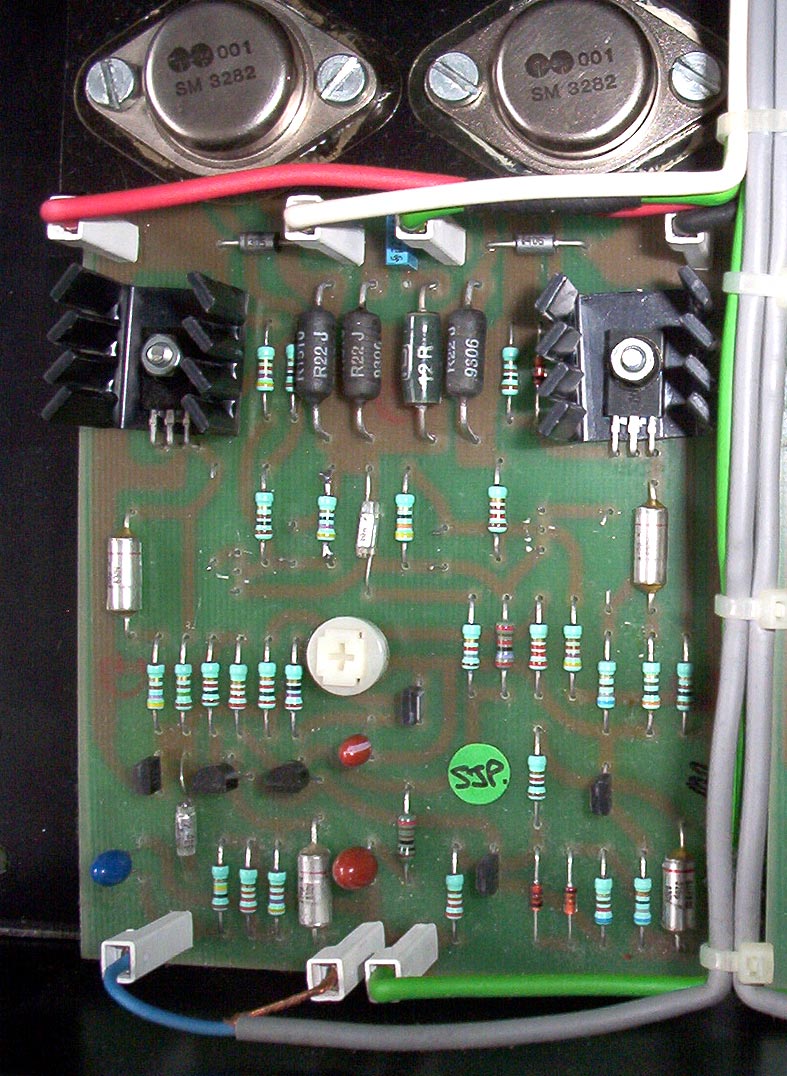
In the above the input cap, C1, is blue, the big red is the feedback, the other is VBE bypass. In all cases I think 'plus' is up.
Perhaps this statement could be checked by an expert?
Paul
This is actually a known issue with the schematic, and the same mistake has been copied by others on their own versions of the schematic. To clarify - the positive leg of C2 (feedback cap) goes to the input ground. The negative leg goes to R3 (1k feedback resistor). Naim originally used one 100uF tantalum here in the 250, but in later amps they would use two 47uF tantalums in parallel - due to reliability issues. Smaller amps like the 140 use a single 47uF tantalum. I've never seen a (standard) Naim amp use a 68uF feedback cap (maybe in some of the super-early models, anyone?). The voltage across this cap is quite small anyway, and a wrongly-connected tantalum cap might still work fine without you even noticing. But do take the time to put it in the right way around! Trust me - you could say that i'm quite familiar with the Naim design.
MJS
Technical Tinkerer
I've not seen 68uF either.
Bear in mind that the hand drawn and CAD versions of the boards have slightly different layouts. If the tant has a face with the markings on it then:
Hand drawn:
10uF SoA tants face to the outer edges on the board
47uF Bias bypass faces the output devices
47//47 or 100uF feedback and 10uF input faces left if output devices are on top - both their +ve leads should be towards the outer edge of the board.
CAD
With output devices at top, all tants face left except the bias bypass tant next to the 1k pot which faces right.
diybry
pfm Member
Thanks SJ, good info, most appreciated. I'm amazed that nobody seems to have previously raised the issue of the incorrect schematic .
To confirm, when you state C3, Can I assume it is the component shown as C2 on the accoustica schematic as per this link?
http://www.acoustica.org.uk/t/naim/poweramp_pix/NAP250 schematic.jpg
I'll use two 47Uf here, my amp currently has a single 100Uf as per your comment
MJS- thanks, this makes it clear for a bodger such as myself. I have hand drawn boards and will be fitting AVX tants, so will follow your advice
as a last question is it worth changing the smaller value caps?
thanks again all
Bryan
diybry
pfm Member
Back up and running Thanks for your help.
The top end brightness, grain and detachment has certainly reduced. Sonds more organic somehow.
I think this more like I remember it sounding back in '84, but it surely cannot be, that was an LP12 not a DAC
Do tants require any 'running in' - can I expect some further changes in SQ?
The top end brightness, grain and detachment has certainly reduced. Sonds more organic somehow.
I think this more like I remember it sounding back in '84, but it surely cannot be, that was an LP12 not a DAC
Do tants require any 'running in' - can I expect some further changes in SQ?
PigletsDad
My intelligence test came back negative.
C1 and C2 don't have much voltage on, so they take a while to form, so slow improvement would be expected.
C3, and the parts in the power supply should mature very quickly.
C3, and the parts in the power supply should mature very quickly.
colasblue
pfm Member
Tantalum caps should be fully formed at manufacture, they do not undergo further (re)formation during use like electrolytic caps.
I would not expect, nor have I ever experienced any tant "run in"
You install them and they work to full SQ instantly (unlike many electrolytic caps).
If you mean by "the smaller caps" the polystyrene ones then in the absence of any fault there is absolutely no point in changing any of them. They don't deteriorate over time.
In my haste when servicing my 135s according to this thread a year ago, I forgot to change the 100uf feedback tants- just got around to doing it this week. My golly what's difference! System really boogies now!!
I used 100uf AVX Tants as I didn't want to drill the holes out for 2 parallel 47uf caps. I figured if the 100uFs fail in 5 years, I can buy two new ones at one pound a piece!
Regards
Matt
I used 100uf AVX Tants as I didn't want to drill the holes out for 2 parallel 47uf caps. I figured if the 100uFs fail in 5 years, I can buy two new ones at one pound a piece!
Regards
Matt