advertisement


Active crossover design musings for E-IIIR

hacker

Delicious and nutritious
Looking forward to the time when I eventually have my nice 3-way Ergo IIIR speakers, I'm preparing a new design of active XO (the old one was a bit crap). Thing is, I have some questions that I don't know how to answer and hoped some of you chaps might be able to help.

I've been chatting to James (the speakers' designer) who has done careful in-situ measurements of the speaker drivers and used that data to run some LSPCad simulations in order to design a customized set of resistor/capacitor filter values for a Linkwitz-Riley 4th order active XO. The XO is tailored to the E-IIIR and provides almost perfect phase alignment at the crossover regions and a practically ruler-flat summed frequency response over the audio spectrum. Which is nice :)

I'm designing the PCB for the XO and want to optimize it as much as possible; this will not be a generic active XO PCB - it's for the E-IIIR only. As such there are some implementation details I could use some help with.

Filter cascading
Rod Elliott's very popular 3-way LR4 XO looks like this:

p09_fig1b.gif


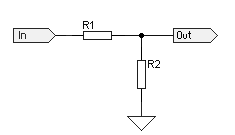
You can see that the low pass (bass) filter takes its signal input from the output of the low-pass section of the bandpass filter. This is because (in Rod's words) if you do not connect them exactly as shown:

Rod Elliott said:
phase shifts through the system will cause the summed output to be different from what you expect. The sections are connected together to give the best outcome - changes will cause unexpected variations, none of which is likely to be good

However, the diagrams generated by LSPCad clearly show that the input to each filter (high, mid, bass) are to be taken from the music "source". For example, here's LSPCad's bandpass filter:

os8QCHH.png


The bass filter also takes its input direct from the source in the LSPCad version:

bs0qjer.png


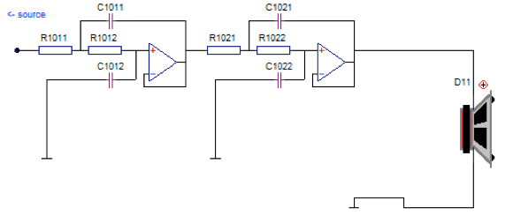
The bandpass diagram differs in 1 very important way from Rod's diagram: It has the high pass section before the low pass section. This is important because in Rod's configuration the input to the bass filter is taken from the the output of the first stage of the bandpass, which in his case is a low-pass filter.

If I was to take the same approach here I'd end up feeding the bass filters from a high pass filter, which would actually remove the lower frequencies, which would completely screw up the bass.

So my though here is this: ignore Rod's diagram and trust that LSPCad knows what its talking about and has taken into account phase shifts and whatnot in its calculations. In other words: Rods schematic is particular to his XO, and LSPCad's schematic is particular to the EIIIR XO.

Any thoughts? James and I have had inconclusive chats about this!

Output Buffers / speaker sensitivity compensation
The drive units in the E-IIIR have the following sensitivity:

Hiqphon OW-1 tweeter: 87dB
Scan-Speak 25W8565-01 woofer: 88dB
Seas M15CH001 midrange: 90dB

As you can see, if I simply connected the active XO outputs to 3 power amps each driver would have a vastly different output level! To correct this I could borrow Rod's idea of using a voltage divider + output buffer opamp at the output of each filter to reduce the levels of the bass and midrange outputs so that they match the tweeter sensitivity. Something like this, where R21 is 10k:

Mh7lBJe.png


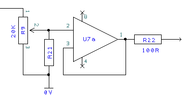
I'd use one buffer for mid (dropping the level by 3dB) and one for the bass (dropping the level by 1dB). The values would be tweaked for preference using the multi-turn trimmers, which would then be replaced with fixed value resistors once I'm happy. The tweeters don't need to have their levels dropped because they have the lowest sensitivity and they're the baseline against which the mid and bass are being adjusted.

Because of this (no need to drop tweeter levels) I'd like to avoid using an output buffer for the treble output - there seems to be no point in having an extra opamp in the signal path - but I have a concern: does a unity-gain unflitered opamp add phase shift? If so, it would seem that omitting an output buffer for treble while using output buffers for mid and bass would lead to unwanted phase shifts in the mid and bass outputs.

Does anyone know the truth of the matter? Should I add an extra output buffer for treble to account for phase shift in the mid and bass?

Alternative level adjustment
Perhaps output buffers are overkill. Would it make sense to instead use voltage dividers at the inputs to the mid and bass filters? In other words: drop the input signal level before the filter sections so that the outputs from the filters are perfectly matched for the drive unit sensitivities.

This seems like a more simple/minimalist solution but I don't know enough to understand any negative side effects of this approach. Help?!?

Sorry for the very long post!
 
Hi Carl

You have answered one of your own questions:

"So my though here is this: ignore Rod's diagram and trust that LSPCad knows what its talking about and has taken into account phase shifts and whatnot in its calculations. In other words: Rods schematic is particular to his XO, and LSPCad's schematic is particular to the EIIIR XO." Rod Elliots design is a textbook implementation and the EIIIR is a custom design for the EIIIR loudspeaker.

I would put a 50K preset pot on the input to each filter (from the source) which will provide options for every eventuality.
You will probably find that you can turn the Bass Pot to maximum (even remove the Bass preset pot if you like) and set the Mid and Treble preset pots to match the Bass. In reality you will probably find the Bass system less efficeint than both the Mid and Treble - YMMV but this is the norm. You will need to calibrate the crossover (acoustically, preferably using a measuring mic) to get the levels for Bass, Mid and Treble correct.

Kind Regards
Peter
 
Rod Elliots design is a textbook implementation and the EIIIR is a custom design for the EIIIR loudspeaker.
Yes and no. Both are LR4 designs. The C/R values are optimised for the E-IIIRs, but the circuit is almost identical. The only difference is whether you implement them as LP/HP -> LP/HP cascaded or LP/BP/HP in parallel. I can't explain if there's likely to be any difference or not.
 
Thanks Peter. I've been toying with the appropriate voltage divider combinations to get me into the right ball-park for correct levels. The idea is this:

* Treble goes unmolested
* Bass is dropped by 1dB
* Mid is dropped by 2dB

Using a standard voltage divider:

QVSMlrU.png


we can calculate the voltage division like so:

vd = 1 + (r1/r2)

And from vd we can calculate the drop in dB:

db = 20 * log10(vd)

I knocked up a quick Perl script to cycle through some "sane" values for r1 and r2 to see which ones came closest to my desired values (1dB and 3dB drops):

Code:
#!/usr/bin/perl

@vals=(10.0,10.2,10.5,10.7,11.0,11.3,11.5,11.8,12.1,12.4,12.7,13.0,13.3,13.7,14.0,14.3,14.7,15.0,15.4,15.8,16.2,16.5,16.9,17.4,17.8,18.2,18.7,19.1,19.6,20.0,20.5,21.0,21.5,22.1,22.6,23.2,23.7,24.3,24.9,25.5,26.1,26.7,27.4,28.0,28.7,29.4,30.1,30.9,31.6,32.4,33.2,34.0,34.8,35.7,36.5,37.4,38.3,39.2,40.2,41.2,42.2,43.2,44.2,45.3,46.4,47.5,48.7,49.9,51.1,52.3,53.6,54.9,56.2,57.6,59.0,60.4,61.9,63.4,64.9,66.5,68.1,69.8,71.5,73.2,75.0,76.8,78.7,80.6,82.5,84.5,86.6,88.7,90.9,93.1,95.3,97.6);

foreach $v1 (@vals) {
	for($r1=$v1*100; $r1<=$v1*1000; $r1*=10) {
		foreach $v2 (@vals) {
			for($r2=$v2*100; $r2<=$v2*1000; $r2*=10) {
				$vd=1+($r1/$r2); 
				$db=20*(log($vd)/log(10)); 
				push @results, "$db = r1=$r1; r2=$r2; \n";
			}
		}
	}
}

print sort(@results);

It goes through the standard 1% resistor values for both r1 and r2, coming up with the dB value for every combination. The list is sorted by value and I filtered out the closest matches:

Code:
./gen.pl |egrep '^(1\.01[0-1]|3\.000)'
1.01036105350144 = r1=1690; r2=13700; 
1.01112746884888 = r1=2000; r2=16200; 
1.01164007099826 = r1=11500; r2=93100; 
1.01164007099826 = r1=1150; r2=9310; 
1.01189896502011 = r1=10700; r2=86600; 
1.01189896502011 = r1=1070; r2=8660; 
1.01195026898572 = r1=2150; r2=17400; 
3.0001266400532 = r1=8870; r2=21500; 
3.00030663963124 = r1=5900; r2=14300; 
3.00057821088251 = r1=1960; r2=4750; 
3.00069518022094 = r1=1370; r2=3320; 
3.00079395310227 = r1=6190; r2=15000;

Excellent! From this we can see that good choices would be to use a voltage divider of R1=1k69 / R1=13k7 for the woofer, and R1=8k87 / R2=21k5 for the midrange.

This assumes a perfect world and I'm very aware that there is no such thing when it comes to making speakers! So I guess I need to find a way to dial it by ear based on these values...
 
* Treble goes unmolested
* Bass is dropped by 1dB
* Mid is dropped by 2dB

This assumes a perfect world and I'm very aware that there is no such thing when it comes to making speakers! So I guess I need to find a way to dial it by ear based on these values...
Carl, you'll have to factor in a degree of baffle step compensation if your E-IIIRs are to live in a free-space, cavity-walled listening room. The bass would need to be full-fat, and the mid and treble dropped substantially. That's what I've done to my passive E-IIIRs.
 
Originally Posted by James
Yes and no. Both are LR4 designs. The C/R values are optimised for the E-IIIRs, but the circuit is almost identical. The only difference is whether you implement them as LP/HP -> LP/HP cascaded or LP/BP/HP in parallel. I can't explain if there's likely to be any difference or not.


Rod Elliot's design is based on ideal textbook response curves and not measured data. It is a generic textbook LR4 crossover implementation.

In Rod Elliot's design the LP filter section is taken from the output of the BP filter's LP section, which introduces a phase shift. From the published data, LSPCad has optimised the design of the EIIIR crossover for LP//BP//HP.

The circuit topology is almost the same (agreed) but as you are (more than most) painfully aware, by manipulating the CR values, the phase and frequency response are optimised for the intended speaker system.
You could take the LP section of the EIIIR from the BP/LP section as in Rod's design but you would have to re-optimise all the CR values to obtain the target phase and frequency responses again.

Thanks Martin for the link, three things stand out immediately:

1 - "The typical parallel arrangement of crossover filters yields a flat summed frequency response only if the constituent highpass and lowpass filter responses are unaffected by adjacent crossover filter sections."
2 - "This parallel filter topology is popular. It is correct for 2-way systems. It usually works for 3-ways when the two xo frequencies are more than a decade apart."
3 - "These phase errors have less impact upon even-order crossover filters where adjacent channels add in-phase, than upon odd-order crossovers where adjacent channels are 90deg out-of-phase."

Carl, check James' response above with regards to the sensitivity settings of the crossover. See if James can perhaps give you an idea of the attenuation he has applied when modelling the active crossovers in LSPCad. You can then set it 'on-the-bench' and be very close to the ideal.
 
A few years ago Rod Elliot sold some of his 4 way LR XO boards at a reduced price because there were some errors on them. I couldn't resist and have had great fun with them. I've bought several drivers cheap from eBay and played around. At the moment I'm using some ribbon tweeters; mid units from some Castle Severn mark II, 10 inch Seas for upper bass and subs going below 50hz. I have not analysed the response of the system yet. I don't know how useful it would prove. I think that the only way to do this properly is with something like this:

http://www.diyaudio.com/forums/digital-line-level/215379-dsp-xover-project-part-2-a.html

These are available now and seem to be very good indeed. Check out Speedysteve's work towards the end of the thread.

Playing around with the ESP unit has taught me that multi- way is definitely the way forward. I hope you get sorted. I will continue to tune the separate drivers by ear for a while. Having 100W directly driving 10" units is great.

Yes there are lots of opamps. However, I am now a big fan of the OPA2134. There is a much clearer sound from this setup than I thought was possible.
 
Carl do you have an adjustable outlet buffer for each section as per Rods site, this will allow you to set relative volumes to each driver the pots can then be measured and replaced with resistors once you are happy.I Am pllaying around with an active byamp 3way using a pair of Marchland boards I got some linear stepped atenuators from China to aid initial set up which I will replace with fixed resistors.
Geoff
 
Forgive me for going off tack slightly, bit it does seem that the traditional has given way to digital ones with much better results, bringing full spectrum phase correction and dsp to the party. Down side is you need multi channel dacs as well as amps.

Look at the mini sharc from minidsp, i2s in and out allowing it to sit between source and dac neatly. Nice thing is that you can fiddle with the crossover parameters until you have it perfect. When you are happy you can measure the room as well and correct for room modes.

Worth a look?

Stefan
 
Carl, you'll have to factor in a degree of baffle step compensation if your E-IIIRs are to live in a free-space, cavity-walled listening room. The bass would need to be full-fat, and the mid and treble dropped substantially. That's what I've done to my passive E-IIIRs.

After googling "baffle step compensation" I realized that I need to go back and google it properly - it seems complicated.

Does the passive XO schematic you sent me incorporate the appropriate baffle step compensation already (albeit tuned to your room)?

Carl do you have an adjustable outlet buffer for each section as per Rods site, this will allow you to set relative volumes to each driver the pots can then be measured and replaced with resistors once you are happy.
That's one of the options, yup. The other option I'm toying with is placing a voltage divider before the input of each filter stage so that I can adjust the signal levels prior to being crossed over. I'd simply use the last opamps in each filter chain as the output buffer, which would mean I could take 6 opamps out of my stereo crossover chain :) (one opamp per filter per channel).

GWM said:
I Am pllaying around with an active byamp 3way using a pair of Marchland boards I got some linear stepped atenuators from China to aid initial set up which I will replace with fixed resistors.

That's a good idea and I much prefer it to multi-turn trimmers in the signal path!

Forgive me for going off tack slightly, bit it does seem that the traditional has given way to digital ones with much better results, bringing full spectrum phase correction and dsp to the party. Down side is you need multi channel dacs as well as amps.

Look at the mini sharc from minidsp, i2s in and out allowing it to sit between source and dac neatly. Nice thing is that you can fiddle with the crossover parameters until you have it perfect. When you are happy you can measure the room as well and correct for room modes.

Worth a look?

Stefan

Those are really interesting but make me hesitate for a couple of reasons. They have either digital (I2S) or analog inputs. If I go for I2S I'd need to place the MiniSHARC between my WaveIO and Buffalo. The MiniSHARC would output 6 channels of digital (left/right for high/med/low), which could be fed into the Buffalo with some reconfiguration, but then I'd need to do 3 lots of stereo I/V, which would mean another pair of Legatos+PSUs... ouch.

I could do analog input to the MiniSHARC but it would then do ADC, DSP, and DAC all over again! At that point the Buffalo/Legato would be irrelevant and I'd be as well just using the WaveIO -> MiniDSP -> HackerNAPs. Hmmm... actually...

...the MiniDSP 2x8 (http://www.minidsp.com/images/documents/Product Brief-miniDSP 2x8 Kit.pdf) will accept I2S inputs (as well as analog inputs!) and provide up to 8x analog outputs, post-processing. It also does digital volume control... No need for Buffalo/Legato/Placids at all! In fact I could sell the Twisted Pear gear, buy the MiniDSP, and still have cash left over for beer and music :D

Food for thought, that's for sure.
 
Those are really interesting but make me hesitate for a couple of reasons. They have either digital (I2S) or analog inputs. If I go for I2S I'd need to place the MiniSHARC between my WaveIO and Buffalo. The MiniSHARC would output 6 channels of digital (left/right for high/med/low), which could be fed into the Buffalo with some reconfiguration, but then I'd need to do 3 lots of stereo I/V, which would mean another pair of Legatos+PSUs... ouch.

Well at least you know the legatos work and you've already done the pain of sorting the PSU for one so just step and repeat!

I could do analog input to the MiniSHARC but it would then do ADC, DSP, and DAC all over again! At that point the Buffalo/Legato would be irrelevant and I'd be as well just using the WaveIO -> MiniDSP -> HackerNAPs. Hmmm... actually...

you could do i2s and analogue input with the AN-FP addon. use the i2s form the waveio for serious listening and the analogue from your deck etc.

...the MiniDSP 2x8 (http://www.minidsp.com/images/documents/Product Brief-miniDSP 2x8 Kit.pdf) will accept I2S inputs (as well as analog inputs!) and provide up to 8x analog outputs, post-processing. It also does digital volume control... No need for Buffalo/Legato/Placids at all! In fact I could sell the Twisted Pear gear, buy the MiniDSP, and still have cash left over for beer and music :D

Food for thought, that's for sure.

not sure the 2x8 does have i2s inputs, you might be able to get to the test points but i'm not sure it's as easy out of the box as the minisharc which was designed with this in mind.

Either way it seems that keeping everything in a digital format until the last minute will introduce the least amount of distortion/harmonics/noise etc

Stefan
 
Beg your pardon, the 2x8 does do i2s. Just what i'm looking for as well.

Seems a good way to go using the on-board dacs, then in the future multi channel ESS dac and I/V stages

Stefan
 
It does seem like a tempting option but for now I think I'll stick with the original plan: custom XO just for the E-IIIRs. I've spent so long building my music source, DAC and amplifiers - not to mention the years of building the E-IIIRs - that I can't bear the thought of abandoning the job right at the last minute!

However, that doesn't mean I can't try out one of those MiniDAC jobbies a year or so from now...

In the meantime, I need to get to grips with:

  • Baffle step compensation. What is it? How does one measure/calculate/implement such a thing?
  • Level adjustment. Voltage divider? Where to implement - at XO filter inputs or at the outputs using opamp buffers? How about using gain instead of attenuation?

I think a good plan of attack is to do this slowly. I'll build the passive XOs and listen to them for a few weeks/months while figuring out what to do with the active XOs. Perhaps I could invest in a cheap measuring rig to help do my own calculations. Lots of options :)

Thanks for the feedback so far, keep it coming!
 
Not sure if you remember Carl I use 2 x P09. They split the treble off first. All have Opamps on the outputs with multi turn pots.

One shift of furniture / speaker and you will want to adjust them slightly.

Perhaps lay out your board to give yourself options. This especially applies to quality of caps, big is often best right?
 
After googling "baffle step compensation" I realized that I need to go back and google it properly - it seems complicated.

Does the passive XO schematic you sent me incorporate the appropriate baffle step compensation already (albeit tuned to your room)?
Yes, both the active and passive circuits I sent you incorporate a 4 or 5 dB attenuation above the midband for the E-IIIR to located away from boundaries.

Baffle step is nothing more than the change from 2pi radiation into 4pi as wavelengths get long enough to wrap around the baffle. This is not usually needed for wall mounts against a solid wall. In free space, and in the absence of room gain, you'd lose 6dB of SPL in the bass compared with treble. For real listening environments, I tend to dial in between 3-5dB.

The last bit of adjustment by ear can be made with trim pots (active) or resistor changes (passive).
 
I think I'm getting it figured out a bit...

In the first Word doc you sent to me there are 2 sets of schematics: one with baffle step compensation, one without. Neither schematic results is a particularly great FR or phase alignment at the XO points.

In the second Word doc, it states "Without baffle step compensation – standard textbook LR4 @ 265Hz and 3kHz", but has very good FR and phase alignment.

Just to confuse me you said above that "both the active and passive circuits I sent you incorporate a 4 or 5 dB attenuation above the midband for the E-IIIR to located away from boundaries."

Can you clarify which schematics have the built-in baffle step compensation and which do not?

Thanks :)
 
Carl,

Can you send me back via email the conflicting word docs I sent you? I'll need to check my LspCAD files. Sorry for the confusion.

James
 
A few random thoughts.

1) Once you have the target gains dialed in, you can make modest gain adjustments at the power amps.

2) If you want, and James simulates this, you may be able to move some poles out of the crossover circuits as such, and simply use small input and/or feedback caps on the power amps.

3) You should not need separate buffer stages; the frequency shaping op-amp runs at close to unity "noise gain", and will have a very low output impedance right across the audio band.


advertisement


Back
Top