advertisement


Parallel Rectifiers?

Mike Hanson

Trying to understand...
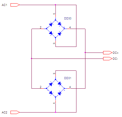
It appears that the Naim NAP250 uses parallel full wave bridge rectifiers. Is this to handle more current, or would this act as fault tolerant redundancy?

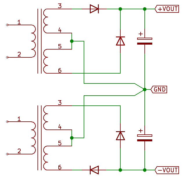
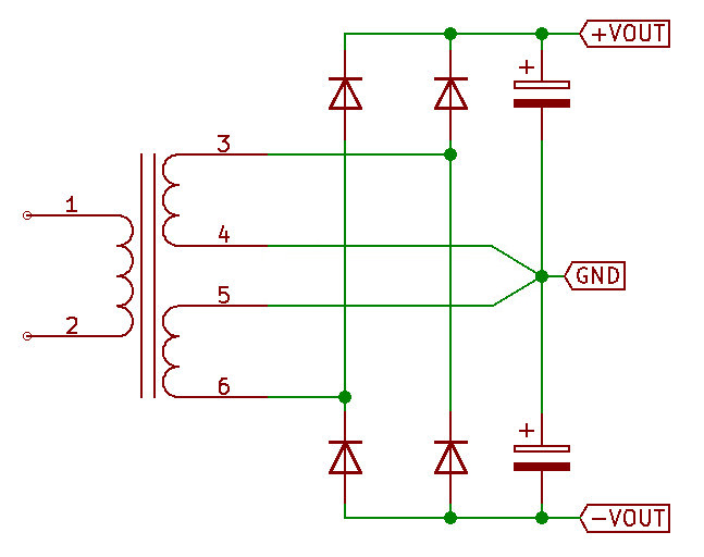
Is this the circuit that would apply?

shI7w.png
 
The traditional NAP250 (and others) use two centre tapped secondaries and the bridge rectifiers are used half-wave, so only two diodes in each are in circuit. Early amps used four discrete diodes, two per rail.

The current(?) NAP250 seems to do something similar but with separate rectification and smoothing per channel. And a lot of secondary windings.
 
The traditional NAP250 (and others) use two centre tapped secondaries and the bridge rectifiers are used half-wave, so only two diodes in each are in circuit.
That is certainly true in my 1990s Hicap (see below). I was never sure what was done in the power-amps though.

The text diagram got reformatted when it went live, though it looked fine when I first created it.
 
Ah, so one secondary feeds the positive rail, while the other feeds the negative (I'm assuming).
Yes, but each secondary is centre tapped. So the centre tap goes to 0v, the outers to the bridge, and either the +ve or -ve output of the bridge to the reservoir cap. Or similar.

It's been like this since the 70s, when there was a pair of individual diodes per channel (these may have been wired the same for each rail, and then connected in series, I'd have to open my power amp to confirm). Why they did this I don't know. It feels good, perhaps 0v bounces around less at mains frequency?
 
The 0V line doesn't go through a diode: does this make a difference in regard to noise?
 
The 0V line doesn't go through a diode: does this make a difference in regard to noise?
A +/- supply, used by a power-amp, usually does get 0V from the transformer centre tap . + & - come from the bridge rectifier.

The Hicap uses a centre tapped transformer too, but it ignores the - output of the rectifier, hence 0V is still direct from the transformer. I believe that is done to reduce noise.
 
  • Like
Reactions: jpk
I still don't get the difference, asked about that some time ago in this thread, here again the pictures, first what Naim used (simulation):

368rkZa.jpg


Now only one winding, again two diodes per rail (simulation):

8k0a1X3.jpg


What's the benefit in using 2 transformer windings???
 
I seem to remember that hicaps and 180s use the same transformer so maybe buying in bulk saves money. Apart from that I can’t think of a good reason.
I use a single centre taped winding so no diodes on the 0v which sounds better to me.


Pete
 
I played around with the simulations and can only see one difference: in the second schematic the diodes are connected to each other between the rails, in the Naim circuit they are totally independent for each rail - maybe this isolates some switching noises...?
 
180's and HC's do not use the same transformer as the 250. The 250 tx has higher secondary voltages.

All naim equipment uses two rectifier diodes on a centre tapped transformer winding as the basic rectifier circuit, similar to JPK's first diagram. They actually install a full bridge rectifier but only use half of it so two diodes are redundant.

The HC has two positive rails rather than a positive and negative.

The reason JV gave for doing it that way 30 or 40 years ago was to do with winding recovery times and hysteresis which somehow led to lower noise if it was done their way.

Since it's a magnetic effect of an imperfect transformer I doubt many modelling packages would correctly simulate it.
 
All naim equipment uses two rectifier diodes on a centre tapped transformer winding as the basic rectifier circuit, similar to JPK's first diagram. They actually install a full bridge rectifier but only use half of it so two diodes are redundant.
Pictures inside the olive NAP250 certainly show what looks like 8 secondary wires feeding 2 bridges and 2 capacitors (JPKs first picture above). That would presumably "waste" half of the transformer's power, which is maybe why people don't replicate it. So there must be some other advantage to this, which makes up for that waste.

Are you gong to give this a trial (please) Mike Hanson? I'd love to know the logic behind this.

The NAP140 is different, as there are 2 bridges and 4 capacitors for the power-amp boards.
 
I still don't get the difference, asked about that some time ago in this thread, here again the pictures, first what Naim used (simulation):

368rkZa.jpg


Now only one winding, again two diodes per rail (simulation):

8k0a1X3.jpg


What's the benefit in using 2 transformer windings???

Absolutely nothing - except as PD noted in post #3 above. The Naim 2-diode 'fullwave' layout only uses half a bridge, but with two secondary windings - instead of a single winding, and a full bridge.


These topologies are identical via superposition; the oft-cited 'benefit of lack of an obvious diode in the 'centre-tap / '0v' side' a complete red herring.
 
But it also uses twice as many windings - and the end result is exactly the same; except as PD's post I reference.

You might need to draw -out the current loops for each part of the cycle to convince yourself of this. ATB


advertisement


Back
Top