advertisement


NCC300 Dual-Mono in a big Case

Here's a question for everyone. I'm building this amp for a friend. His mains are terrible, so he's considering buying a Power Plant from PS Audio. He can get the P3 or P5 used. He would prefer the P3, as it's newer, but it can produce only 300W continuous, 500W for 30 second bursts, and occasionally peaks of 1000W. The P5 can do 1000W continuous.

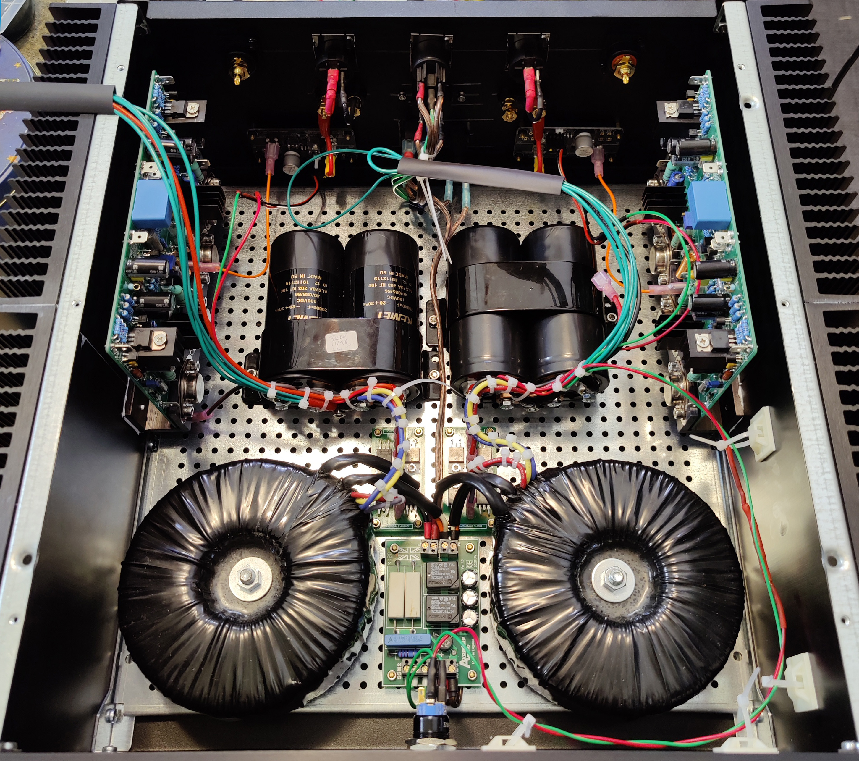
That makes me wonder how much power this NCC300 dual mono build is going to draw. He's driving pretty big speakers and he likes to turn it up. Les has indicated that a NCC300 mono amp can put out 130-140W, but I don't expect that to be expected in "normal" usage. Also, that's output power, and I'm assuming that there's a fair bit lost to inefficiency. Any guesses as to the real load from the power amp, so we can determine how much is left over for everything else?
 
Last edited:
However, I've found the top and bottom 3mm aluminum panels break this pattern. You need to get them oriented

No that's not it Mike
I'm fully aware of the top/bottom panel fit
The issue I was referring to was the left/right side pieces being pulled out of vertical by screwing the base infill panel into place
If that makes sense?
 
Most of the parts are in (except for the speaker protection modules on the back panel, because I have to solder a couple of spades connectors to the board). I'll likely have that together later this week, so that I can start wiring and testing this weekend.

AlmostPopulated.jpg
Is it just me or these large Kemet reservoir capacitors really seem to be the best value for money nowadays ?
And despite their low cost, quality is on par with any other high end manufacturers.
 
No that's not it Mike
I'm fully aware of the top/bottom panel fit
The issue I was referring to was the left/right side pieces being pulled out of vertical by screwing the base infill panel into place
If that makes sense?
I hadn't noticed that myself.
 
Is it just me or these large Kemet reservoir capacitors really seem to be the best value for money nowadays ?
And despite their low cost, quality is on par with any other high end manufacturers.
These came from Avondale with the NCC300 boards and related bits for the build (via a friend who decided I was more eager to do it). Therefore, it's was an easy choice. ;)

I just realized that I have another two pairs (15k rather than 20k), that I bought for another build, so I guess I agree with you. :D
 
I wasn't a big fan of the modushop cases base either...but on balance...the extra strength and the lack of holes needed in the aluminium base make it worth it
The main problem I found with them was the need to bend the base to get the case sides to line up properly

Not just me that found the inner base a real pain at time, aligning holes and making it difficult to align the case. On balance it does provide substantial strength to the case.
 
I've started wiring and testing:
  • Both power inputs (switched between IEC and PowerCON) flow through to the SSM.
  • SSM powers up and feeds through to its output.
  • Both transformers are connected to the SSM.
  • Right channel transformer connected through the bridge rectifier into the capacitor pair, and are reading 62.5V - 0 - 62.5VDC.
I've got a concern at this point: Les recommended 40-0-40VAC transformers, which is what I have. The NCC300 docs warn "that the absolute maximum voltage that may be applied to the circuits is 60-0-60VDC, measured off load." Canadian mains are supposed be 120VAC, but mine are a bit high at 125VAC.

Do I need to change gears and use a different set of transformers?
Just make sure you don’t drop a screwdriver between a positive and negative post !
My Musical Fidelity P170 runs at 60 VDC which was a surprise to me but seems to be okay. I replaced some 5 watt fuses with 12 watts as they were running at 125 Celsius and the 12 watts now run at 85 Celsius.
In your situation, I would use another transformer to give you the proper voltage.
Some Naim amps run at 37 VDC and they don’t show any signs of lack of power.
 
Mike any excess voltage can be just adjusted down on the on board regs
There should be no issue with dropping a few volts and indeed I've found none....using 42-0-42 on mine giving 65v to the boards...this is then wound back to 57v on mine
No sign of heat stress and no overheating anywhere

Don't forget you need a few volts headroom for the regs to work properly!
This is the supply for the whole board, not just the front end. I realize I could dial back the voltage on the input side. Can I do it for the whole board?
 
Ohh yes I had forgotten you were using the link pins / jumpers.

In that case the regs will adjust the voltage to the whole board then??
Problem solved ?? Or have I got that wrong.
 
The regs supply the front end only. I have the same issue here in the uk with high mains voltage so I ordered transformers with lower voltage secondary windings. After reading the Tiger Toroids threads I might order new transformers with primary windings to suit my mains but tbh I'm not having any issues with the Airlink ones already fitted.
 
I've started wiring and testing:
  • Both power inputs (switched between IEC and PowerCON) flow through to the SSM.
  • SSM powers up and feeds through to its output.
  • Both transformers are connected to the SSM.
  • Right channel transformer connected through the bridge rectifier into the capacitor pair, and are reading 62.5V - 0 - 62.5VDC.
I've got a concern at this point: Les recommended 40-0-40VAC transformers, which is what I have. The NCC300 docs warn "that the absolute maximum voltage that may be applied to the circuits is 60-0-60VDC, measured off load." Canadian mains are supposed be 120VAC, but mine are a bit high at 125VAC.

Do I need to change gears and use a different set of transformers?

I would have thought that the only reason to be concerned about the extra couple of volts is the rating of the caps (63V?).
I think I've made myself unpopular on here by expressing concern about the high voltages some are using, but once you are up that high, a couple of volts shouldn't make much difference as long as the caps are appropriately rated.

If you have a 5W 1K resistor you could try sticking it across one of the 62.5V rails to see what the voltages drops to with 60mA of load current.
I would also suggest checking your mains at various times. If it goes up to e.g. 130V at any point you could be in trouble.
 
Here's a snapshot of the latest progress. All the wires are strung, although I've not connected the power to the NCC300 modules yet, given my concern about transformer voltage. (I plan to talk with Avondale tomorrow.) Fortunately I have another set of transformers that are 35-0-35 rather than 40-0-40, with the same footprint, so swapping them won't be tough. They have extra windings that might be useful in another build, though, so I would rather use the ones that are there now.

The power switch LED works (with a 100K resistor inline), connected to one channel's positive rail. The speaker protection modules are also wired up (again powered directly from each channel's positive rail).

WiringUnderwayPonderingTransformer.jpg
 
I've spoken with Avondale, and they've confirmed that 62.5V is definitely too high for the output stage. I didn't want to use my spare transformers, as they have additional secondaries beyond the 35-0-35V needed for this build, making them well suited for a Voyager configuration. Fortunately I have an alternate plan to move forward.

I realized that I have an earlier dual mono QUDOS build that suffered a failure, which I've not had the opportunity to diagnose. I can salvage its pair of 35-0-35V 250VA transformers, and move ahead with this NCC300 build (for my friend who's arriving later this week).

It also made me realize that I'm nowhere near finished my amplifier building days. :D
 
It also made me realize that I'm nowhere near finished my amplifier building days. :D

You can check-out but you can never leave :eek::D:
https://pinkfishmedia.net/forum/threads/kicking-this-dirty-habit.82791/

I currently have:
NCC300 in bits waiting to be reconfigured
PCB design for my version of a SYMEF amp nearly complete
PCB design for 15W class A FET amp nearly complete (matching cap multiplier PCB to be designed). These amp boards will replace the Pass Aleph boards currently on my BIG heatsinks.
Only Music OM2.7 needs moving from the 'cuckoo's nest chassis' to a decent box.
Mini-Goldmund amp - need to decide if it's good enough to go in a box.

I will stop soon. I promise!
 
I will stop soon. I promise!
I know your pain. :D

In addition to this NCC300 dual mono build, I have my own NCC300 monos underway, a QUDOS amp that needs fixing, a Voyager amp in the planning stages, a little Tripath amp that I might do for fun, and I'm musing about the possibility of a Class A amp (using those big Plitron transformers that keep getting punted down the field).

That and my PFM Special speakers that I've promised I'll do this winter. :rolleyes:
 
The replacement transformers are 330VA Avel Lindbergs, so a fair bit smaller than the 500VA Plitrons.

Transformer%20Comparison.jpg


advertisement


Back
Top