advertisement


NCC300 Dual-Mono in a big Case

Mike Hanson

Trying to understand...
I was able to get the parts for another NCC300 build from a friend who decided I was more eager than he was. I'm building it for another friend of mine, who's coming to visit in a few weeks. I'm hoping to have it done in time for him to take it home with him.

It's going to be put into a big 4U Dissipante case, so I have lots of space to play with. Here are a couple of possible layouts:

Layout1.jpg
Layout2.jpg


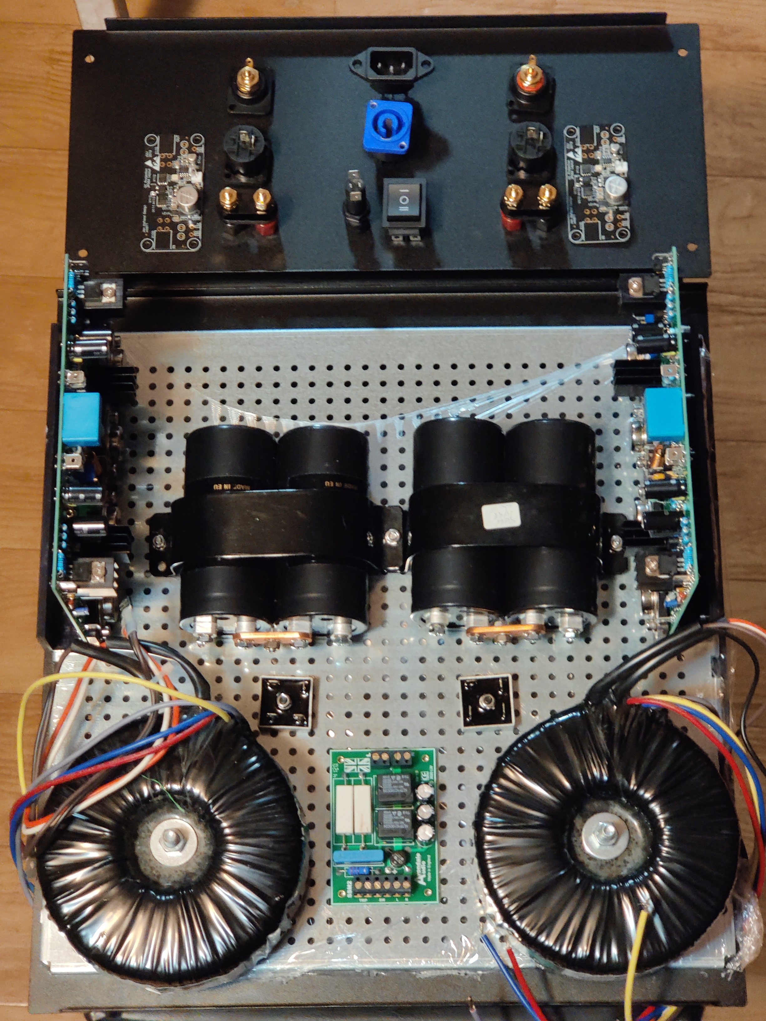
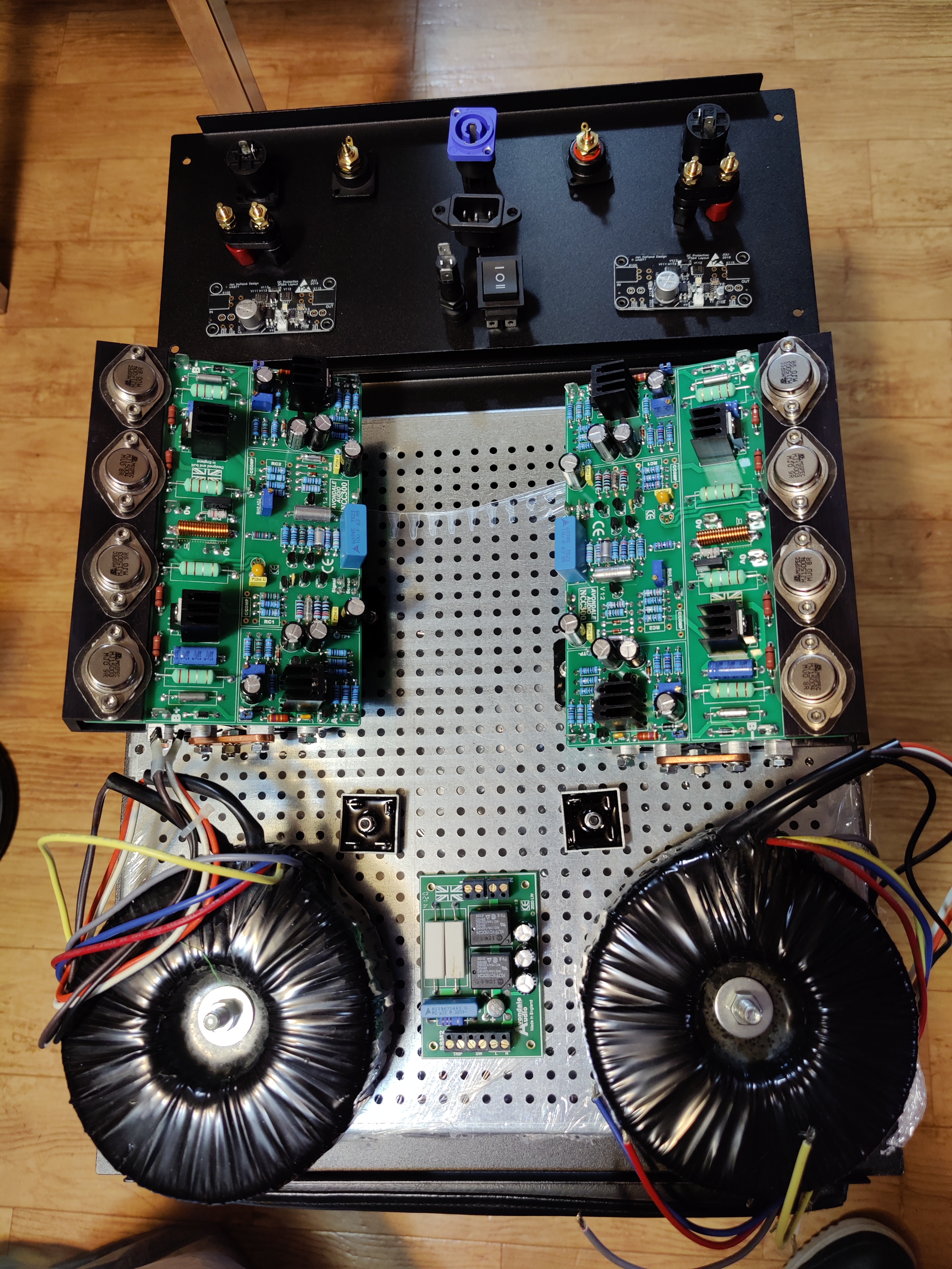
I'm not settled yet on whether to mount the NCC300 modules facing inward (as in the first picture) or facing up, with the caps hiding below. There's plenty of room in the case to do it either way. I like that the first layout keeps the amp modules far away from everything else, but I'm unsure if it's going to be trouble with them sideways like that. I'll probably go with #1, unless someone here convinces me that it's a terrible idea.

Regarding the components:
  • The transformers from my friend had more secondaries than I needed for this build. I happened to have these Plitron 500VA units spare, each with dual 40V secondaries. I can join them to get 40V-0-40V, which is perfect for the NCC300.
  • That's an Avondale SSM2.
  • The bridge rectifiers are holding the place of Avondale modules with discrete Schottky diodes (kicking around here somewhere). The capacitors are 20,000µF Kemets.
  • I prefer Neutrik connectors, but my buddy likes IEC for power and 5-way binding posts for speakers, so I'm adding both. (There's so much space on the back panel!) That rocker switch in the middle will toggle between power sockets.
  • The speaker protection modules are the first gen of these. They're powered directly from the main DC supply, saving me the trouble of installing another transformer for a UPC1237 module.
I'm still pondering power supplies. What's likely to be better?
  • Avondale Bridge Rectifier with 20,000µF of Kemet caps
  • HackerCap with ON-Semi rectifiers and 30,000µF of Chemi-Con caps (probably with 10mH inductors between each bank of caps)
Ready... Set... Go!
 
Way to go Mike,

I'd go with less uF (I run one pair of 300s with 10kuF per rail.) and NO inductors needed between the caps, their not required on the output (IMO) and the on board regs negate the need for the inductors. (again IMO) But its your build..:)
 
I prefer the layout number 1 as it will be easier to see what’s going on if any diagnosis or repair has to be done.
Nevertheless, I would put the output transistors upward to make sure the heat is not transferred to surrounding components.
And like laverda, I also prefer going without inductors, always seems to me an amp sounds punchier without them although I'm not 100% convinced it has any effect in a power supply.
 
I would put the output transistors upward to make sure the heat is not transferred to surrounding components.
I hadn't considered that. Would the heat rising through the air have that significant of an impact?

The reason I had the other edge up was to keep the input section away from all the noise in the bottom.
 
It's a very old story that bears repeating, always: Keep the loop-area between the transformer secondaries, the rectifiers and the big reservoirs as very, very small as you can. that means-physically-small distances; keeping the wire loops in which current flows there-and-back twisted (at 3x per inch min); and really thinking that whole aspect through. And, very esp, ensuring that anything on the clean/amplifier side after the reservoir caps does not share a common impedance with the raw dc charging the reservoir caps.

Happy to help there.

Everything else can be managed; but this is your biggest source of EMI, and less-than-optimum outcomes, by far. Extraneous LF magnetic induction and unwanted inclusion of voltages from peaky charging currents in a shared loop - if you don't keep it in check - will ruin everything else, more readily than anything else.

It's the source of the problems noted in the phono stage build next door, already noted by several others.
 
I hadn't considered that. Would the heat rising through the air have that significant of an impact?

The reason I had the other edge up was to keep the input section away from all the noise in the bottom.
Then I would install the boards horizontally instead as heat is the enemy of electrolytic capacitors. I would also try to install the reservoir capacitors in such way they are easy to see and remove if needed, maybe closer to the transformers.
OTOH, some output transistors remain warm although when pushed hard so might not be a major concern.
Naim got rid of this problem by using the whole casing as a heat sink so this is another option.
 
Surely your going to mount the board heatsinks to the case heatsink?
And the only way is with the boards outward?
 
And, very esp, ensuring that anything on the clean/amplifier side after the reservoir caps does not share a common impedance with the raw dc charging the reservoir caps.
I'm not sure that I understand this. If I'm using the single pair of caps per channel, then the dirty and clean sides are the same thing.
 
Then I would install the boards horizontally instead as heat is the enemy of electrolytic capacitors.
The whole point of the heat spreader and sink is to wick the heat away. I would think that the bit emanating from the surface of the power transistors into the air won't increase the ambient internal temperature appreciably, at least not enough to damage something.

I would also try to install the reservoir capacitors in such way they are easy to see and remove if needed, maybe closer to the transformers.
That's another reason why I would want to have the NCC300 units mounted against the sides (the first layout), so that the caps are more accessible. They'll be placed as close as possible to the rectifier and transformer.
 
interested in the protection modules especially if they can be powered by the DC supply
The speaker protection circuit in my stereo Sugden also runs off the (main) output transistor PSU, AND is common to both outputs; the two output relay coils are in parallel.

It's based on the old Hitachi HA12002, but the newer (compatible) NTE1635 is still available.

(I have nearly traced the whole circuit :) )

BugBear
 
Hmmm. I'm not saying the you and Martin are wrong, but when I look at Avondale's builds, I don't recall seeing twisted lines (except for the audio-in, in the case of an unshielded twisted pair). He does use lots of cable ties to keep the runs close together though. Does that work toward the same goal?
 
Last edited:
This is how not to do it....not a twisted pair in sight.

49610843011_36ab2e333c_k_d.jpg

The biggest issue with this build is that the bias generating transistor is not thermally connected to either the drivers or the output transistors. The bias current will most likely vary a lot with temperature and there is a distinct possibility of thermal runaway (which is my guess at the root cause of most of the "unexplained" NCC failures).
 
which is my guess at the root cause of most of the "unexplained" NCC failures

What did I miss...? I've built over ten pairs of 300s over the past few years, (for me, family and friends) some with and some without the bias transistor strapped to the heat spreader, all are still working and in daily use.

The one in the above photo was the first dual mono (voyager) I built way back (rather threw together, as you can tell, late 2017) just to see. I have now transferred the same amp boards into monoblocks powered by SMPS's. In use ever day.

See the section here on "Thermal Stability":
https://www.richardmudhar.com/blog/2017/01/
 
I don't recall seeing twisted lines (except for the audio-in, in the case of an shielded twisted pair). He does use lots of cable ties to keep the runs close together though. Does that work toward the same goal?
Yes, exactly that -it keeps the cross-sectional area of the loop each set of current flows-around to an utter minimum. And that minimises the potential for magnetic induction between such loops, which is what dominates hum/ unwanted psu harmonics issues (buzz/fizz issues are usually more blatant and obvious in cause - though the mechanisms can be closely related)

Mike - re your other query above to me - I'll try to remember to do small sketch /other diagram to clarify my point on avoiding shared impedances between 'clean' and dirty/raw psu charging currents tomorrow. It will not surprise you at all... you'll recognise the logic.


advertisement


Back
Top