advertisement


Switch on the Onix OA21S

stackowax

pfm Member
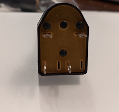
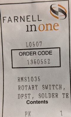
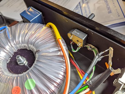
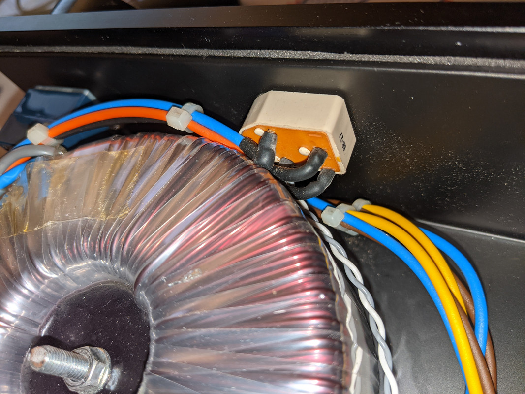
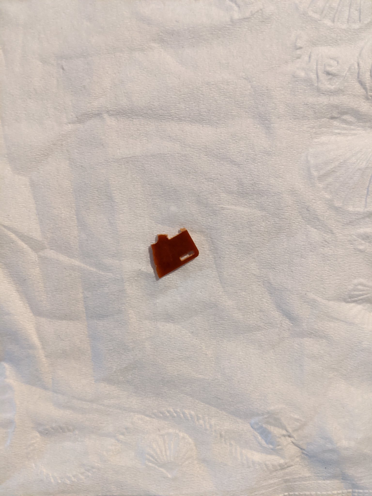
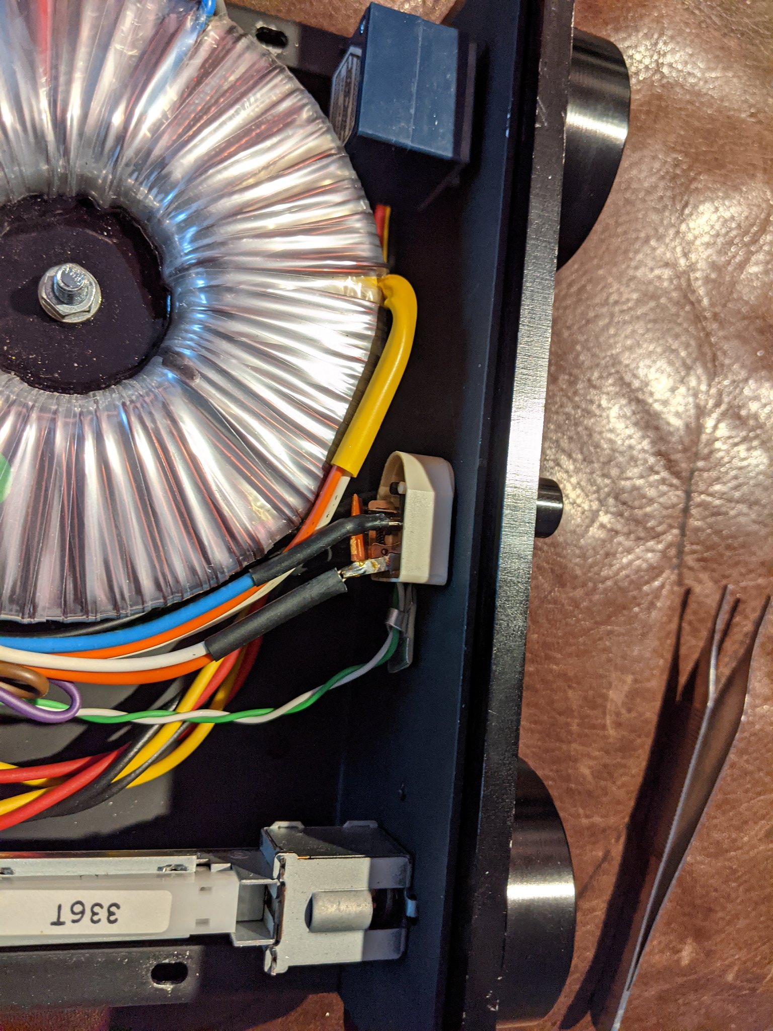
Anybody know where to find a replacement on/off switch for the OA21S. I just bought a used one (obviously) and the back of the switch seems to have fallen part during shipping. The top photo is of a piece of the back of the switch that was rattling around in the case. The lower photo is of the switch itself. Apologies in advance for the size of the photos. I couldn't figure out how to make smaller.
50947830722_11ae54338e_k.jpg
50947830687_28f0a14101_k.jpg
 
There is a set screw, although loosening it doesn't release the knob (that's true of the other knobs too--volume, source selector). So I can't really see the spindle. The set screw is on the bottom of the switch, so I guess that is the 90 degree spindle. But, as you say, there's no obvious way to order different spindles.
 
If it has a set screw it should be good with round or flatted types. I replaced one on an old Naim amp where the switch shaft was round and the knob had a flat. But the shafts are plastic so you can file flats onto them if you need to.
 
If it has a set screw it should be good with round or flatted types. I replaced one on an old Naim amp where the switch shaft was round and the knob had a flat. But the shafts are plastic so you can file flats onto them if you need to.

That's good because I had already ordered the round type :)
 
Great. Now for the hard part. Is it possible to determine which wire from the transformer goes to which solder tab on the switch? I don't know in what order the original wires were soldered to the tabs, but I know that single wires were soldered to two tabs and pairs of wires were soldered to the other two tabs. Here's the breakdown of that arrangement:

White/Orange wires soldered to a single tab.
Green/Black wires soldered to a second tab.
Brown wire soldered to a third tab.
Blue wire soldered to a fourth tab.

If it helps, his the orientation of the switch as installed.

Note that one pair of solder tabs is perpendicular to other pair of solder tabs.


50953578951_3cf95151a6_w.jpg


For a better look at the solder tab arrangement see the first pic in post #10 above.

One more thing, the transformer is 120V (I'm in the US).
 
I replaced the same switch in a Naim NAP140 and kept photos for reference so I can probably help. Please wait for someone else to verify before acting on my guidance!

I'm assuming brown and blue come from the IEC inlet (maybe via a fuse). These connect to the two tabs at the squared end of the switch. Then the paired up transformer primaries connect to the two tabs at the rounded end. Orange/white to one tab and green/black to the other, and it shouldn't matter which connects to which.

Having looked, you're right that the brown and blue are coming from the IEC inlet. So is it also true (pending verification from others!) that it also doesn't matter which tabs on the squared end of the switch the blue and brown wires are attached to?
 
Having looked, you're right that the brown and blue are coming from the IEC inlet. So is it also true (pending verification from others!) that it also doesn't matter which tabs on the squared end of the switch the blue and brown wires are attached to?
That's right. And if you have problems with wires reaching in this configuration, you could also swap round end to square end (e.g. brown and blue to round end, and transformer wires to square end).

Of course the crucial thing is to make sure brown and blue don't connect to each other! :)
 
Hi,
I've got oa21s 220V and the switch is wired like this:
Brown - bottom left (close to the round side)
Blue - top left (close to the round side)
Orange - top right (close to flat side)
Black - bottom right (close to the flat side)

Round is pointing towards the volume pot, like on your picture.

Brown and blue come from the IEC inlet.

I am trying to figure out how to upload a picture...
 
It might be unclear what's going where but unless the trafo is out it's difficult to take a picture from under.

Just occurred to me that if you have a multimeter you can check the replacement switch for continuity and identify the pairs. Connecting the probes to each pin and turning on/off you will find the live-to-live and neutral-to-neutral. I think the direction of the pins is already indicating that. On my switch the IEC wires (blue brown) are on the round side, the two pins are inline.


advertisement


Back
Top