
You are using an out of date browser. It may not display this or other websites correctly.
You should upgrade or use an alternative browser.
You should upgrade or use an alternative browser.
Revisiting Jim Rogers JR149s
ToTo Man
the band not the dog
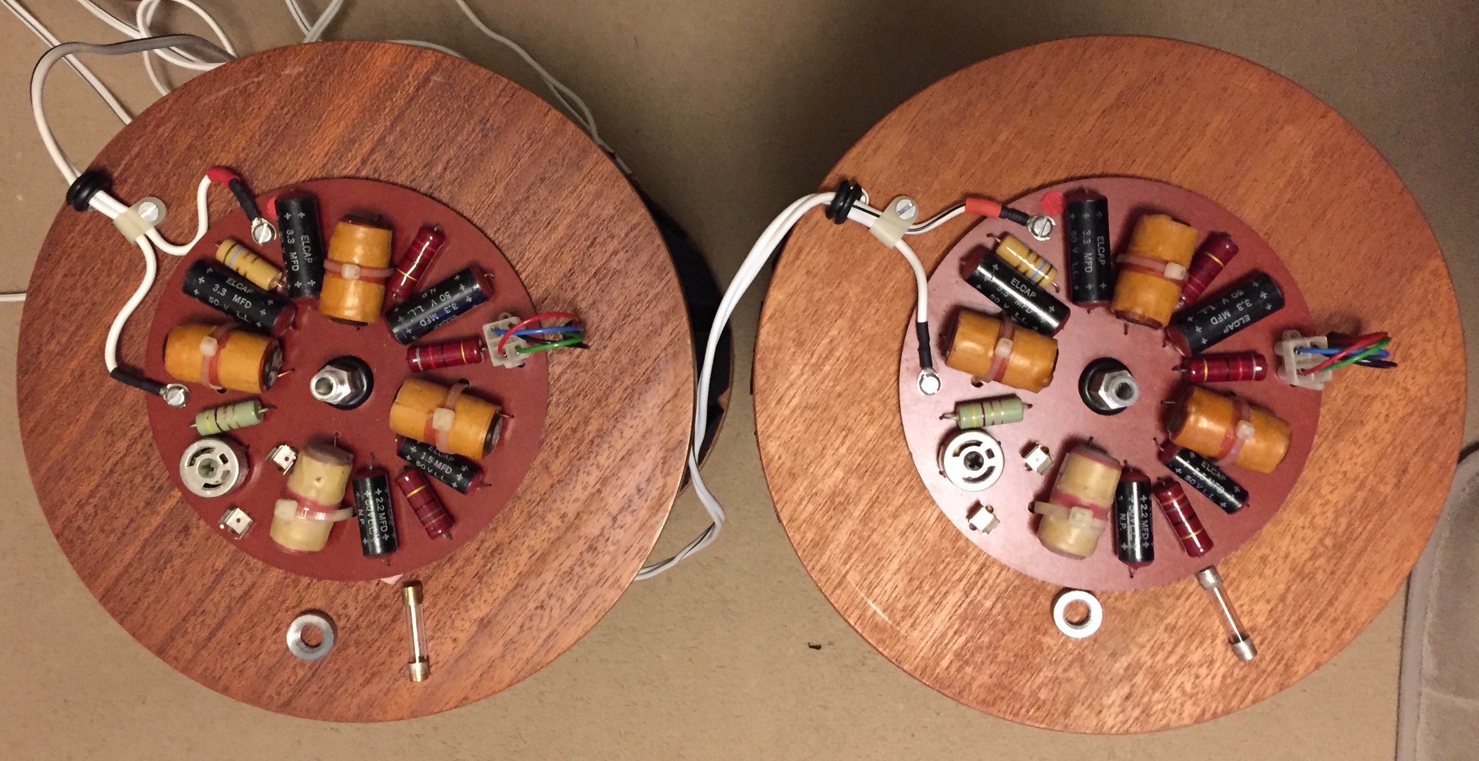
I realise I'm probably a few months (or even years?!) too late with this info, but as I was replacing the stock 1.5A fuses in my JR149 mk1's with 50A versions I thought I'd snap some crossover pics to contribute the pfm JR149 database.
As far as I can see, the left and right units from each pairing have identical capacitor and resistor values, but the resistor values are different between the pairs. Also, I hadn't noticed before but one of my pairs has rather ugly fuse holders predominately made from plastic, with wires running through to the other side of the board. I presume this is as it would have left the factory as I can't see someone going to the bother of replacing the fuse holders?
I also still have the original crossovers from my very first pair of JR149 mk1's (I sold this pair with Type 24 crossovers installed), but I'm not sure where these are at the moment. I'll add a photo of these tomorrow if I can locate them
Pair A:
Pair B:
Tony L
Administrator
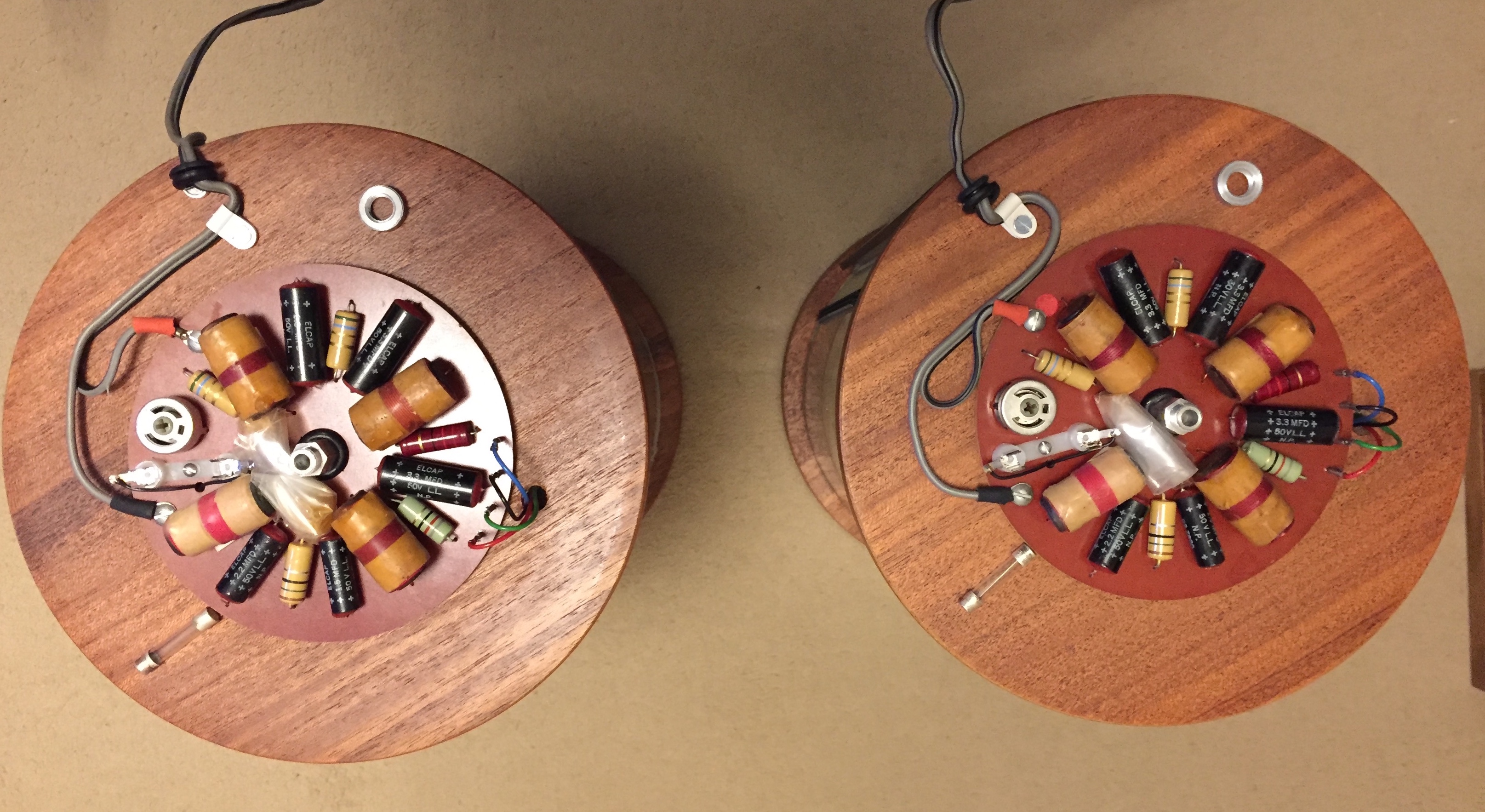
Fascinating. It is clear we are dealing with at least three different boards here:
a) Red logo no fuse, in-line soldered driver connections.
b) Fuse, soldered in-line driver connections.
c) Fuse, square plug-fit driver connections.
Can you possibly detail what differs component value-wise from the schematic here and on which of the two crossovers? My colour sense isn’t really up to reading resistor bands, let alone in pictures!
ToTo Man
the band not the dog
My eyes aren't the best either, especially under artificial lighting, but I'll have a go and report back. If anyone else wants to give me a second opinion it would be greatly appreciated!Fascinating. It is clear we are dealing with at least three different boards here:
a) Red logo no fuse, in-line soldered driver connections.
b) Fuse, soldered in-line driver connections.
c) Fuse, square plug-fit driver connections.
Can you possibly detail what differs component value-wise from the schematic here and on which of the two crossovers? My colour sense isn’t really up to reading resistor bands, let alone in pictures!
PS - You can't tell from the overhead photo but the hook up cables on the second pair aren't soldered to the crossover board pins, they use the same crimp-on lugs as in the square plug, minus the plug.
Elephantears
Trunkated Aesthete
A 52 page thread on foam grilles; I'm impressed!
But can I but in to ask for advice on sourcing a good pair of JR149. I have it in mind to compare a pair of KEF LS50 Meta with some JR149s. I've just, quite impulsively, ordered a pair of the KEFs from Amazon, with the intention of sending them back within the 30 days allowed (unless I fall in love with them). I've not been so curious about a new speaker for years. It would be great to compare them with one of the all time great small speakers.
So should I get Mk 2? Anything important to look out for? And what kind of price is right?
Tony L
Administrator
I suspect the context between the 149 and LS50 will be so different other factors will make the choice for you. The 149 will need to sit closer to a wall and the kind of amplifier is very different, the 149 being high impedance like an LS3/5A and a perfect match for a really nice valve amp, the LS50 needing some solid state heft to get the best out of it. Both great speakers IMO (though I’ve yet to hear the Meta version of the 50).
As for sourcing JR149s, condition is everything IMO, and sadly it is very hard to find really nice pairs. The good thing about the Mk I is they can be fully rebuilt as the Kef drivers are in production by Falcon. From what I hear from Totoman the Mk IIs seem stable though. There are certainly a lot more Mk Is around. If you don’t have a preference I’d just buy in condition. Even then you may have some work to do. Mine are the tidiest pair I’ve seen, but even then they needed a full rebuild to get them to the point they genuinely compare to a new pair of LS3/5As (I have no idea which I prefer!).
As for sourcing JR149s, condition is everything IMO, and sadly it is very hard to find really nice pairs. The good thing about the Mk I is they can be fully rebuilt as the Kef drivers are in production by Falcon. From what I hear from Totoman the Mk IIs seem stable though. There are certainly a lot more Mk Is around. If you don’t have a preference I’d just buy in condition. Even then you may have some work to do. Mine are the tidiest pair I’ve seen, but even then they needed a full rebuild to get them to the point they genuinely compare to a new pair of LS3/5As (I have no idea which I prefer!).
Stunsworth
pfm Member
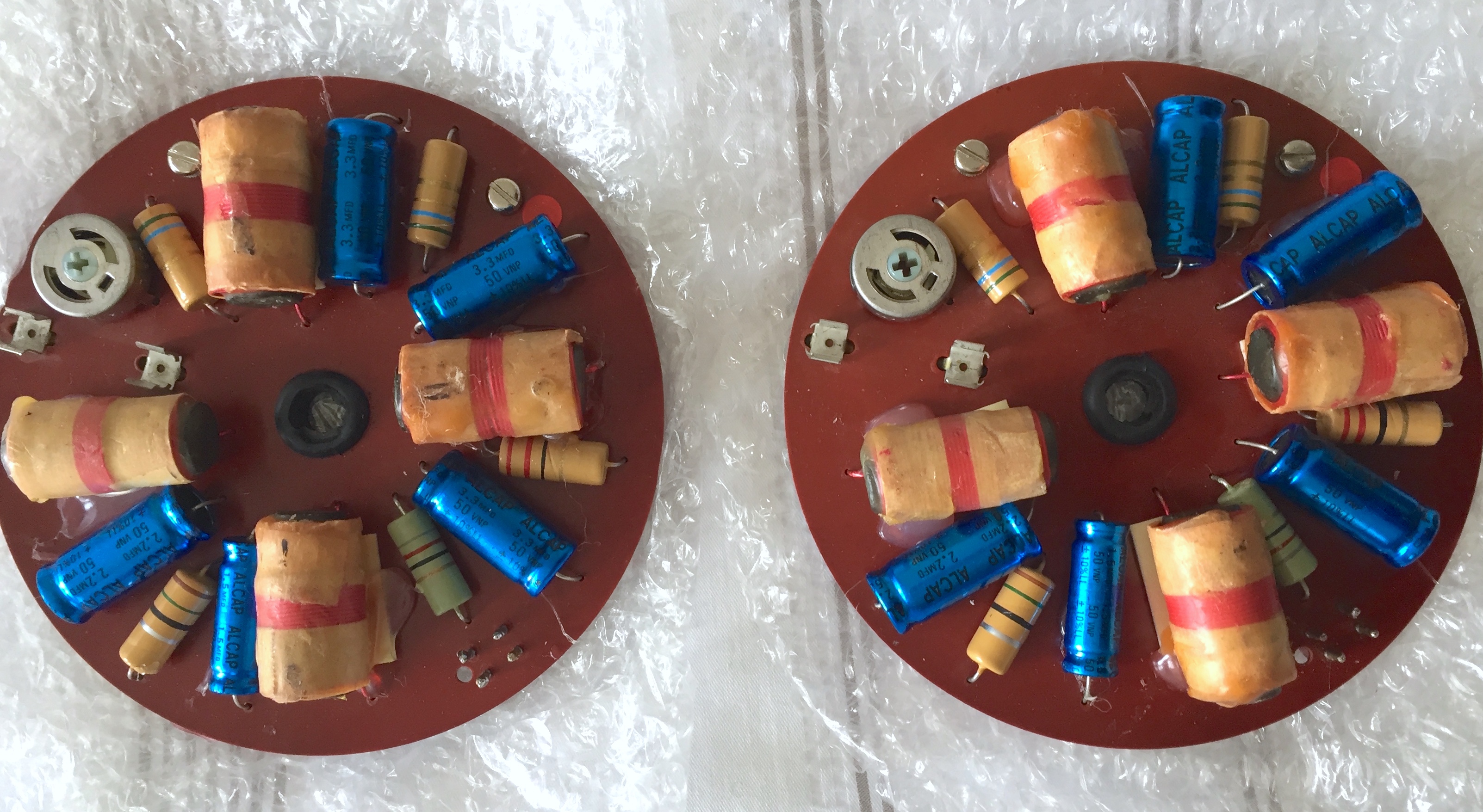
I’m obviously pretty useless at this, but my best guess is the one that is different between the two crossover types is the one near the tweeter level pot. I’d love to know if either matches the schematic though.
I could be wrong, but it looks as if the two resistors are the same, but switched by 180 degrees.
ToTo Man
the band not the dog
I think Tony's referring to my two photos in post #1022, not #1025.I could be wrong, but it looks as if the two resistors are the same, but switched by 180 degrees.
ToTo Man
the band not the dog
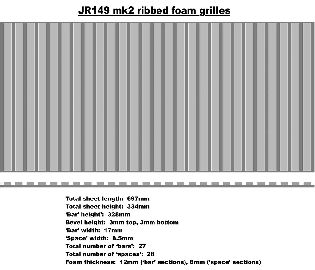
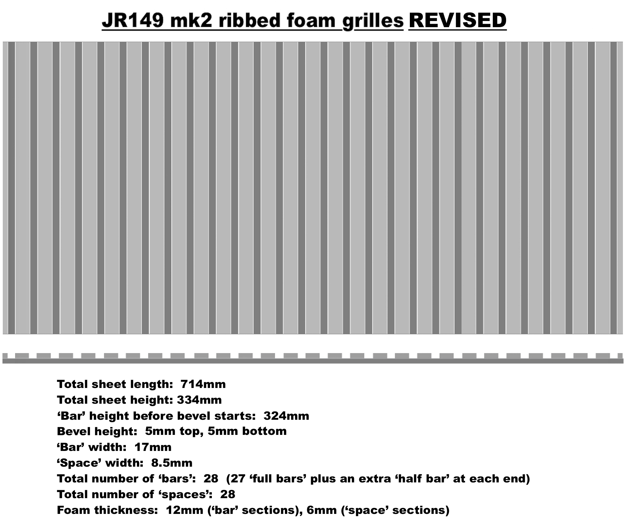
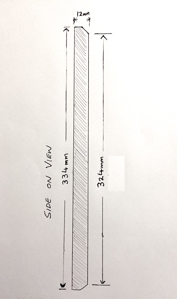
This is now the final version of the foam grilles I'm having made for my mk2's. I'd unconsciously conflated part of the original mk1 grille in my previous drawing with a flat channel strip running top and bottom. The mk2 does not have this, the 'bars' run all the way to the edges, but start to bevel inwards (reduce in thickness that is, not width) a few mm's from the edge. The height of the bevel on my original mk2 grille looks to be about 3mm, but this is hardly visible from the listening seat so I've asked Graham to expand the bevel from 3mm to 5mm. I have also yet again increased the total length of the grille from 697mm to 714mm, by including an extra 'half bar' at each end, just to be absolutely sure it's going to be long enough. Better too long than too short, - I can always trim it down to the perfect length myself if necessary.
Graham is making a total of 6 sets of these grilles. I've committed to purchase 3 sets, which will leave 3 sets available to others, so please get in touch with him if you want one of the remaining sets. I've been informed that lead time will be around 3 weeks.
Disclaimers: I have measured and designed these grilles to the best of my ability but cannot guarantee that they will be a perfect fit for your mk2's. Also I am not receiving any commission or other financial incentives on orders for these grilles, I supplied my design FOC to Graham and have also published it here on the forum so anyone can use it as they wish.
Last edited:
TonyScarlett
pfm Member
What looks like a very early pair of red logo JR149s (s/n 1575) are ending tonight. They look in pretty good condition;
https://www.ebay.co.uk/itm/Rogers-JR-149-Loudspeakers-Mk1-Red-Logo-/254864207073?campid=5338728743
Interestingly they look as if they have had some but not all of the caps replaced. Will be interesting to see what they eventually sell for.
TS
https://www.ebay.co.uk/itm/Rogers-JR-149-Loudspeakers-Mk1-Red-Logo-/254864207073?campid=5338728743
Interestingly they look as if they have had some but not all of the caps replaced. Will be interesting to see what they eventually sell for.
TS
This site contains affiliate links for which pink fish media may be compensated.
Elephantears
Trunkated Aesthete
What looks like a very early pair of red logo JR149s (s/n 1575) are ending tonight. They look in pretty good condition;
https://www.ebay.co.uk/itm/Rogers-JR-149-Loudspeakers-Mk1-Red-Logo-/254864207073?campid=5338728743
Interestingly they look as if they have had some but not all of the caps replaced. Will be interesting to see what they eventually sell for.
TS
Shhh!
I'll probably leave it though as I've got these LS50 Meta in the house now and I suspect that, in the realm of LS3/5A derivatives, these may be definitive.
This site contains affiliate links for which pink fish media may be compensated.
S-Man
StrivingON
Shhh!
I'll probably leave it though as I've got these LS50 Meta in the house now and I suspect that, in the realm of LS3/5A derivatives, these may be definitive.
Looking forward to your impressions of the Metas!!
TonyScarlett
pfm Member
Just had another look at the photographs I took of the crossovers in my original pair of JR149s & compared them to the circuit diagram Tony linked to in post #1023. The 4R7 resistor nearest the tweeter trimpot in mine was 5R6, the same as the next resistor around. The values in the the pair I currently have are correct.
Would this (relatively small) difference in values make any difference to the sound? My impression with my current pair is they don't quite have the same bass extension as my first pair although obviously this could be down to several factors (including, of course, poor audio memory).
TS
Would this (relatively small) difference in values make any difference to the sound? My impression with my current pair is they don't quite have the same bass extension as my first pair although obviously this could be down to several factors (including, of course, poor audio memory).
TS
TonyScarlett
pfm Member
Had another look at that circuit diagram, I'm assuming that changing the 4R7 resistor to 5R6 would have the same affect as turning the tweeter level down which could be why I perceived a higher bass output in my 1st pair (I set the tweeter trimpot to the dead centre position in both pairs).
Going to have a play with the trimpot positions tomorrow, see how much difference it actually makes.
TS
Going to have a play with the trimpot positions tomorrow, see how much difference it actually makes.
TS
TonyScarlett
pfm Member
Set my trimpots to the 2 o'clock pos as you suggested, definitely improves the balance, they are sounding much more as I remembered my 1st pair now.I definitely like some treble cut in mine, I’m a good way off the centre point, somewhere around two o’clock IIRC (clockwise is cut).
While I had the covers off I thought I would see what the resistors were actually reading with my DMM, these are the results;
4R7 measuring 4.2R & 4.0R
5R6 measuring 4.3R & 4.3R
22R measuring 0.8R & 0.7R??
82R measuring 0.5R & 0.4R??
15R measuring 8.8R & 10.6R
As you can see the 22R & 82 R resistors are measuring miles out. Am I doing something wrong with my measuring? I thought it was OK to measure resistors while they are still in the circuit or am I wrong?
Assuming my measurements are correct then it seems a new set of resistors are in order. What wattage are they & does anyone have suggestions for suitable makes & types for crossovers?
Thanks,
TS
Tony L
Administrator
I suspect it is just that they are in circuit. If you didn’t already try disconnecting the drivers and see if you get a different reading. I’d expect them to be bang on, I’m sure the ones I removed from mine were, even the burned ones in the replacement pair of crossovers I used for testing fancy caps. The problem with my pair was they were mismatched from the factory, some differences right to left, so I replaced all resistors with Kiwame, which are well regarded carbon film types. I chose these mainly as they have the values written on rather than the colour codes that I struggle to read! Pictures of my crossovers can be found upthread (the best sound I got was with the Alcaps from Falcon).