
Jeff Young
pfm Member
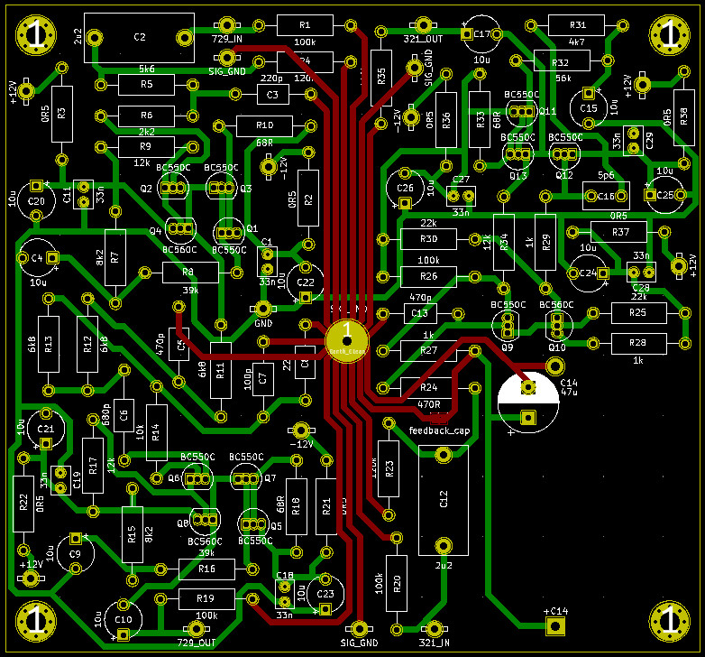
Yep. The HackerCAP is CRCRC.
[Or at least it looks like it from the board. I don't see a schematic for it.]
[Or at least it looks like it from the board. I don't see a schematic for it.]
Yep. The HackerCAP is CRCRC.
[Or at least it looks like it from the board. I don't see a schematic for it.]

Andy, thanks a lot! So I will try the following:
Jpk, download coil32, its a Windows based coil simulator, let's you play with all variables.
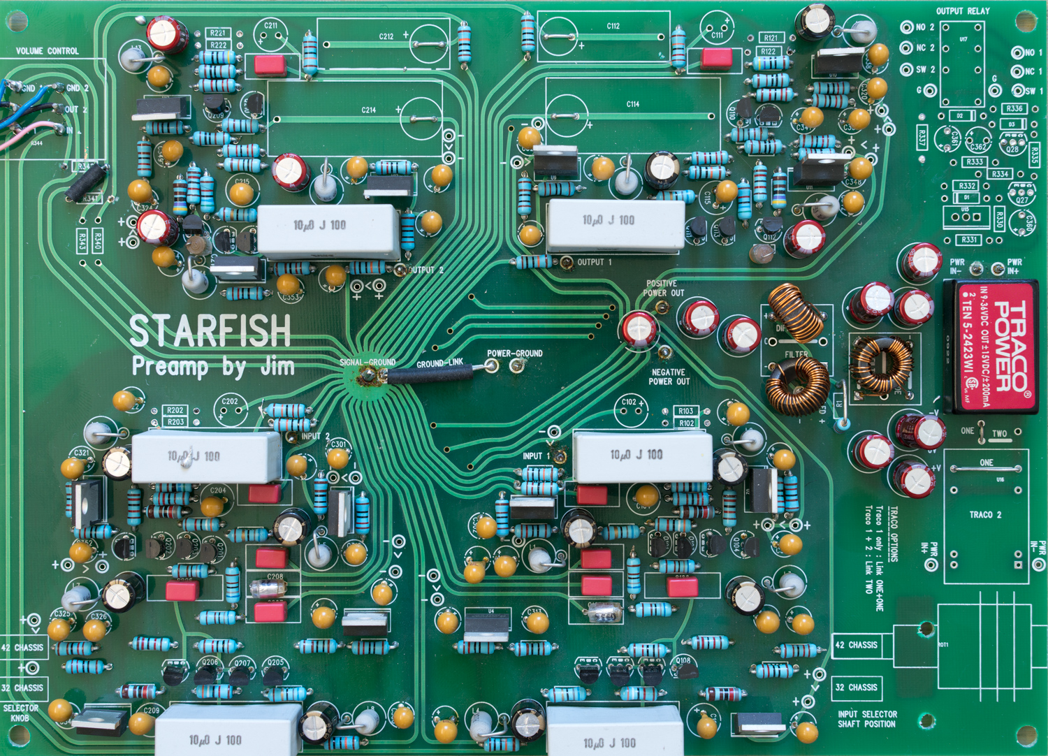

I ditched my traco for a pair of super teddy regs sounds much better.
No I only have the build manual. But it was easy to lift one end of the psu chokes and solder the wires in.
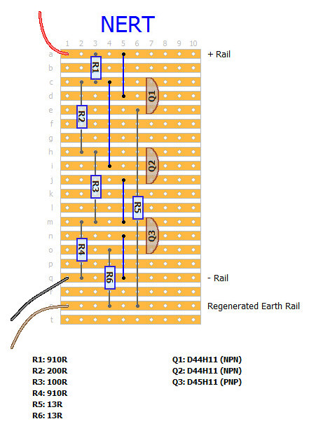
I used a pair of super teddy regs positive and negative so I could remove the nert all it does is create an artificial 0v.
No, not the original one. I tried hard to find one but was lucky enough to get the fully built one. I ordered PCBs of my layout though so I will have spare boards, but yet they are untested. Do you want to populate and test them?