
Radford Revival
Trade: Radford Revival

There is a small error on this - the 800p capacitor should be 500p/470p!


Brilliant, thanks!
 P1110603 by Michael Pickwell, on Flickr
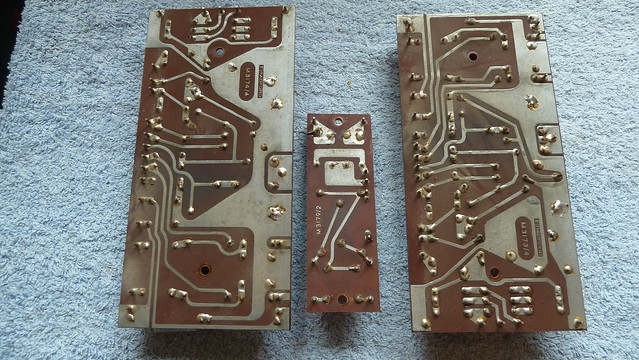 P1110607 by Michael Pickwell, on Flickr
 P1110608 by Michael Pickwell, on Flickr
What are suitable easy to find modern replacements for the four DD058 diodes?
Cheers.UF4007 (low noise version of the ubiquitous 1N4007)
Edit: Certainly no need for ferrites anywhere around these either!
UF4007 (low noise version of the ubiquitous 1N4007)
Edit: Certainly no need for ferrites anywhere around these either!
")
This morning I tested all of the resistors and on the boards and found that they were generally well within spec still. There are only a few that I'm going to bother replacing and even those aren't far out.
Can anyone tell me what the minimum power handling and voltage requirements are for R32 (68K), R9 (33K) and R31 (8K2)?
I intend to replace all of the electrolytic caps but out of curiosity I measured a bunch and found that they were also remarkably within spec too.
On that subject: I've noticed that the new improved boards have significantly higher capacitance for most of the electrolytics than the original circuit diagram e.g. 100uf vs 50uF for C4, 470uF vs 250uF for C12+C11 etc. Any advice as to whether I should stick to the original values for upgrade to the higher values?
I tend to use 3W resistors for the 68K and 33K screen divider supply, and 2W for the 8K2. Technically higher than they need to be but they run warm so good to be a bit overkill here. I also use 2W resistors for the phase splitter anode loads (33k and 39k), as well as the 8k2 common cathode resistor. Originally they are under-specced and you often find they are discoloured in STAs with heavy use.
100uF in the position of C4 has a bit of a tradeoff - it does increase loop gain at LF so technically you get a slightly better damping factor at around 20Hz, but at the expensive of a slightly less damped LF pole with the feedback loop closed. Nowadays I have gone back to 47/50uF in that position, I ought really to remove that picture from the website, it is incredibly out of date.
As for the high voltage caps I now just use 10uF good quality 450V caps as I buy them in bulk.
On the STA25 the bypass capacitor value doesn't matter too much as it's in parallel with such a low value resistor in the cathode, I just use 220uF now but going higher won't cause any harm. It is however possible to overdo it on the STA15 as it moves the pole-zero pair a bit close to the others as experience has taught, bigger isn't always better.
My STA15 is still stuffed full of those silver TCC jobbies, some dated 1965. Only one failed to make the cut when it was serviced two years ago.I intend to replace all of the electrolytic caps but out of curiosity I measured a bunch and found that they were also remarkably within spec too.
I've now ordered most of the parts I need but I'm struggling to find anywhere that has stock of F&T 8uf+8uF dual section capacitors that I want to use.
Excellent, I'll order from them tomorrow. Thanks!Found these at a company called Modulus £4.80.Picture shows 15+15uf but they do 8+8
 P1110611 by Michael Pickwell, on Flickr
 P1110615 by Michael Pickwell, on Flickr
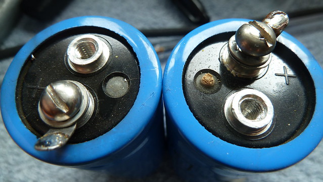 P1110620 by Michael Pickwell, on Flickr
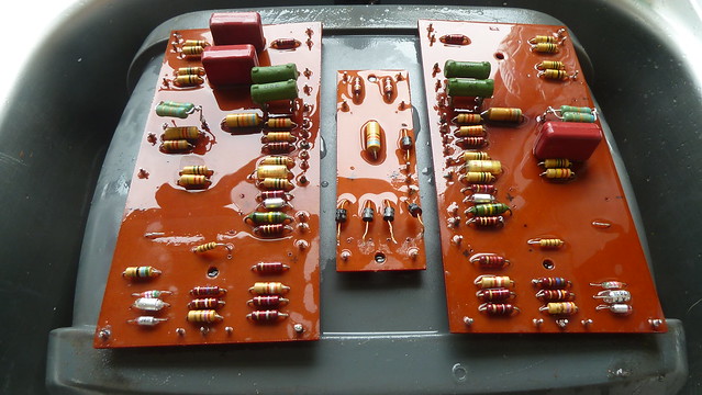 P1110624 by Michael Pickwell, on Flickr
Yes I'd noticed that but thanks for checking with me though!I note your main capacitors were 450V rated - really you need 500V rated electrolytics for the main HT supply.
 P1110632 by Michael Pickwell, on Flickr
 P1110628 by Michael Pickwell, on Flickr
 P1110625 by Michael Pickwell, on Flickr
 P1110627 by Michael Pickwell, on Flickr