Mike P
Trade: Pickwell Audio
Like the title says, I have just bought a Radford STA25. Eeek!
The seller had powered it up slowly on a variac and briefly demonstrated it to me with some small cheap bookshelf speakers but other than that it hasn't been tested or properly assessed.
I'm new to Radfords, and still quite new to valve amps in general if I'm honest, so any advice on assessing the amp would be gratefully received.
So, here it is:
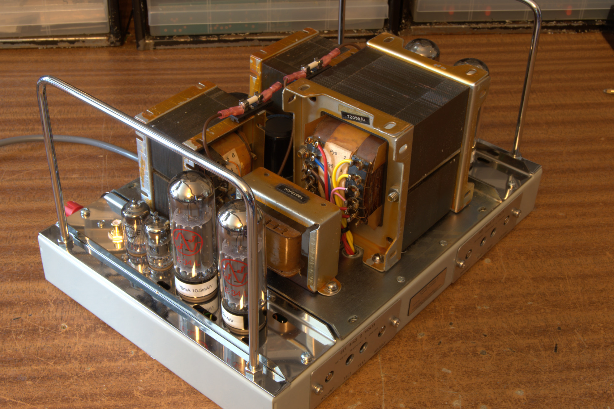
 P1110580 by Michael Pickwell, on Flickr
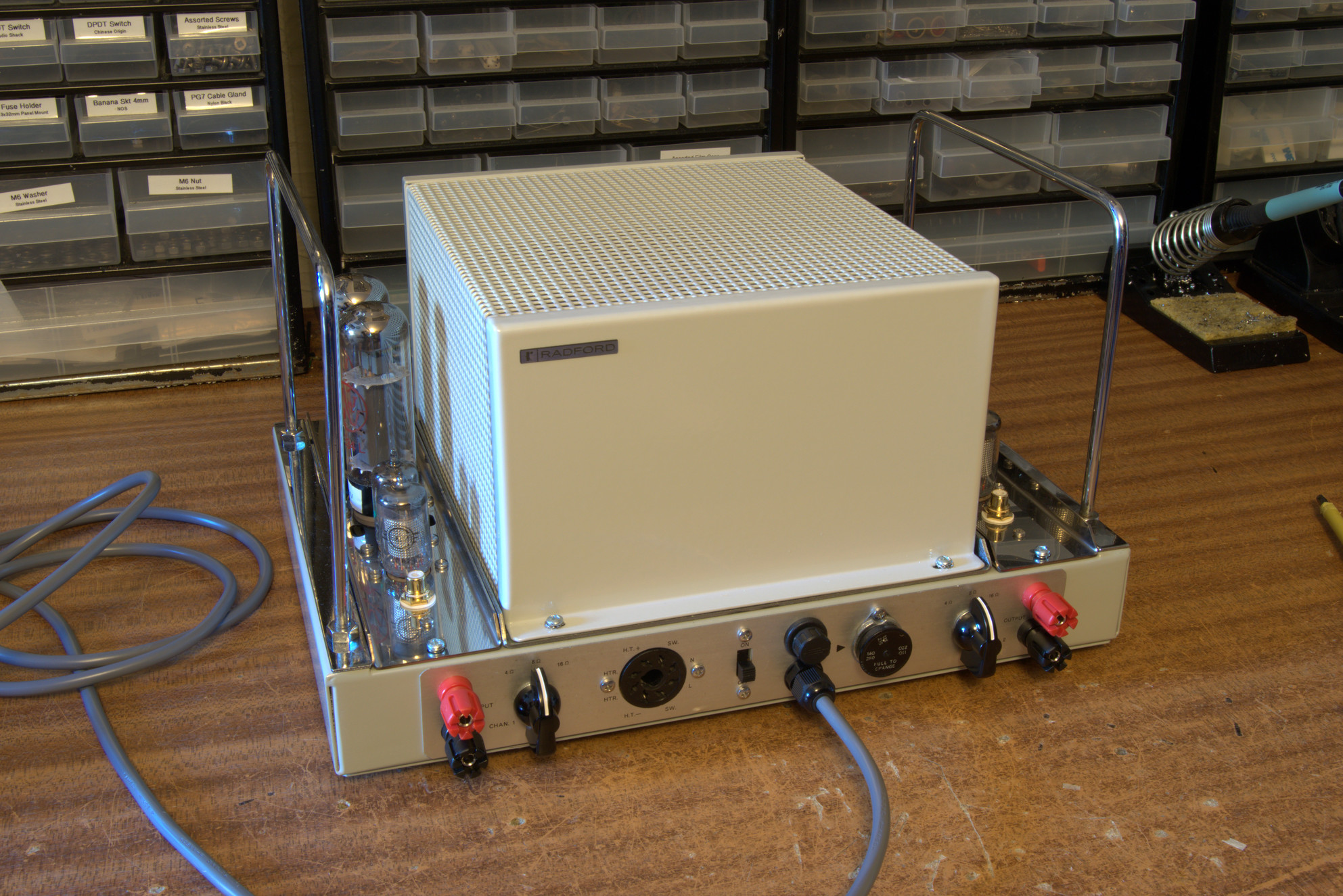
All looks to be Kosher to me under the cover.
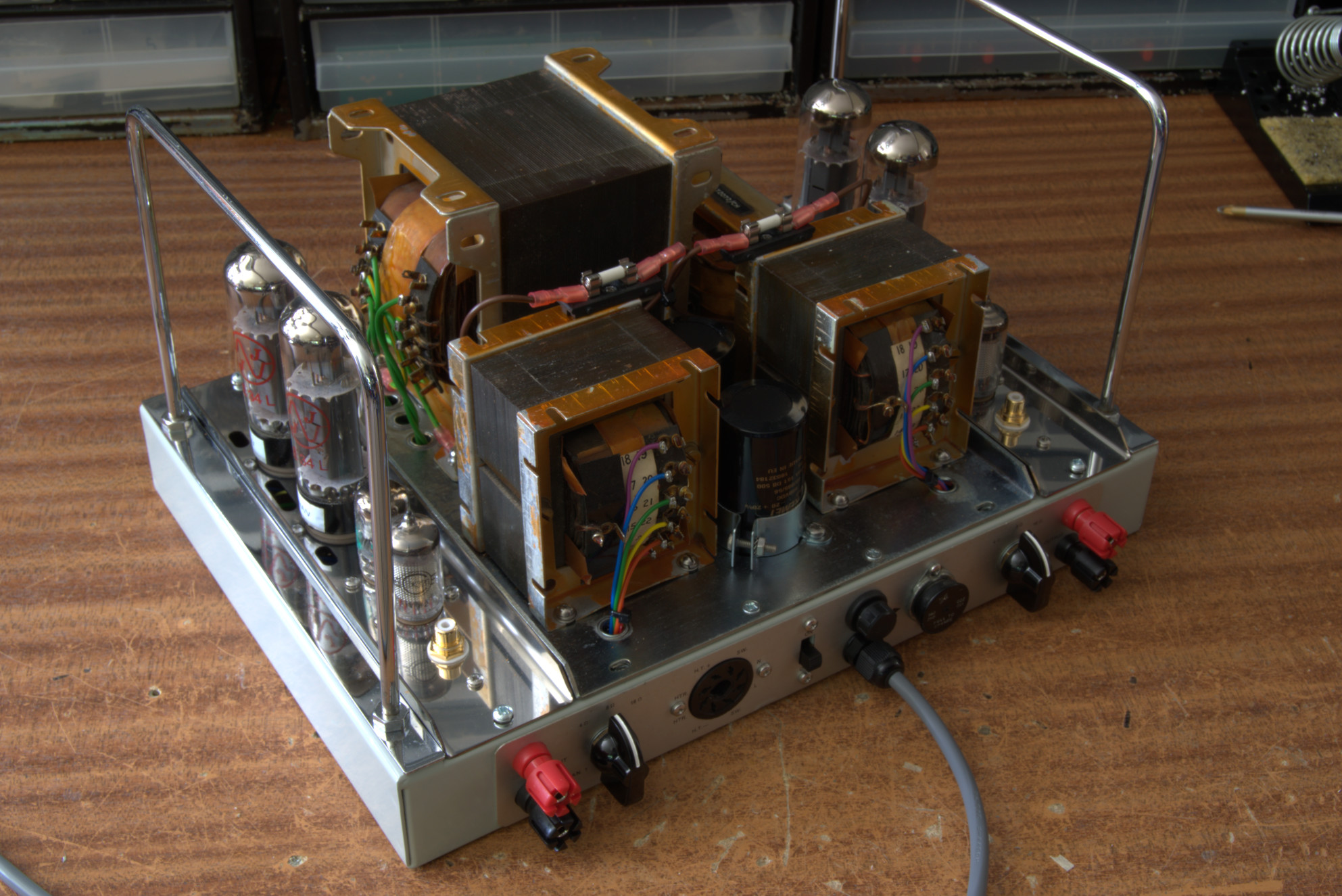
 P1110572 by Michael Pickwell, on Flickr
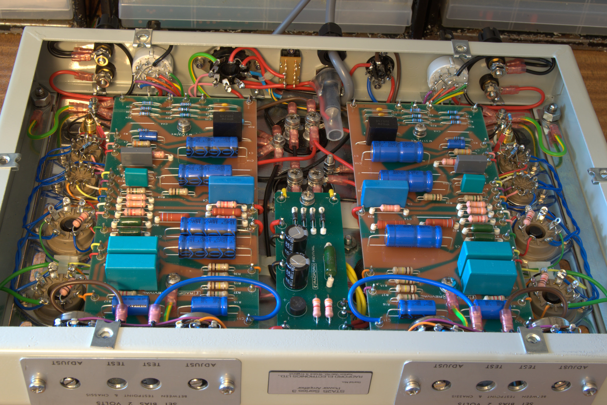
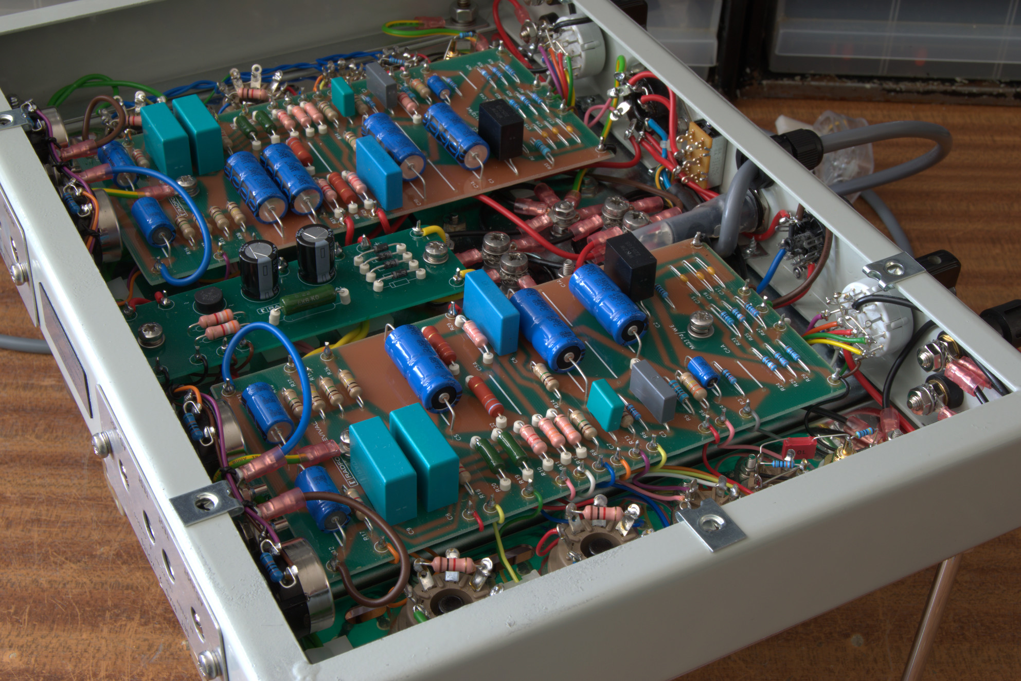
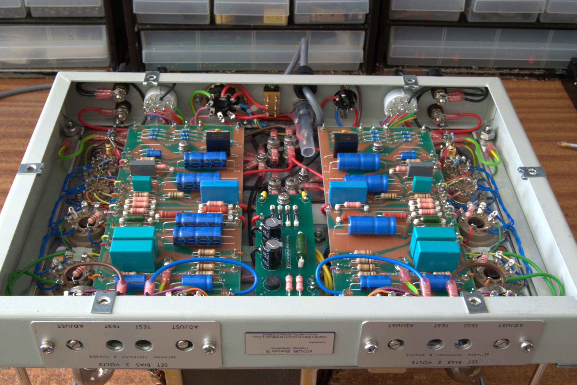
And here's the circuit boards:
 P1110571 by Michael Pickwell, on Flickr
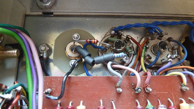
The spark supressor has obviously gone pop at some point.
 P1110568 by Michael Pickwell, on Flickr
And it looks like someone has emptied their collection of ferrites into it!
 P1110569 by Michael Pickwell, on Flickr
 P1110570 by Michael Pickwell, on Flickr
The small valves are all Mullards
 P1110575 by Michael Pickwell, on Flickr
 P1110576 by Michael Pickwell, on Flickr
But the four EL34's are a mixed bunch.
 P1110574 by Michael Pickwell, on Flickr
Second from left is obviously branded Chelmer. The one on the far left looks to be the same construction but is slightly shorter. The third from left is a Mullard XF2. I've no idea what the one on the far right is.
So, there we have it. Peach or lemon?
The seller had powered it up slowly on a variac and briefly demonstrated it to me with some small cheap bookshelf speakers but other than that it hasn't been tested or properly assessed.
I'm new to Radfords, and still quite new to valve amps in general if I'm honest, so any advice on assessing the amp would be gratefully received.
So, here it is:
P1110580 by Michael Pickwell, on FlickrAll looks to be Kosher to me under the cover.
P1110572 by Michael Pickwell, on FlickrAnd here's the circuit boards:
P1110571 by Michael Pickwell, on FlickrThe spark supressor has obviously gone pop at some point.
P1110568 by Michael Pickwell, on FlickrAnd it looks like someone has emptied their collection of ferrites into it!
P1110569 by Michael Pickwell, on FlickrP1110570 by Michael Pickwell, on FlickrThe small valves are all Mullards
P1110575 by Michael Pickwell, on FlickrP1110576 by Michael Pickwell, on FlickrBut the four EL34's are a mixed bunch.
P1110574 by Michael Pickwell, on FlickrSecond from left is obviously branded Chelmer. The one on the far left looks to be the same construction but is slightly shorter. The third from left is a Mullard XF2. I've no idea what the one on the far right is.
So, there we have it. Peach or lemon?
Last edited:
 P1110578