
Arkless Electronics
Trade: Amp design and repairs.
Can you remind me, what parts of this do you think are wrong?
What part of that, beyond saying you are wrong, I am not going to discuss it as we've been there before, do you not get?
Can you remind me, what parts of this do you think are wrong?
This is getting on for half my lifetime ago so my memory is a bit fuzzy, but as I recall our studio was pretty much exclusively single-ended. We had a Soundcraft Spirit Studio 16/8/2 desk, the muti-track recorder was an Alesis ADAT (an early digital 8 track that recorded to a SVHS tape!) and a rack of outboard kit (digital reverbs, delays, compressors etc). I am certain all that lot was wired up with bog-standard mono 1/4” jack plugs, a right bloody rats nest to be honest. Its only recently I went through what was left of the cables that had been sitting in my cellar for ages and flung a bin-sack full of filthy junk out, and none were TRS jacks. I can remember the couple of XLRs we had were used one on the JP6 and the others were just mic leads!
What part of that, beyond saying you are wrong, I am not going to discuss it as we've been there before, do you not get?
")
This is one channel of a fully balanced Class A/B amplifier, too many components ?
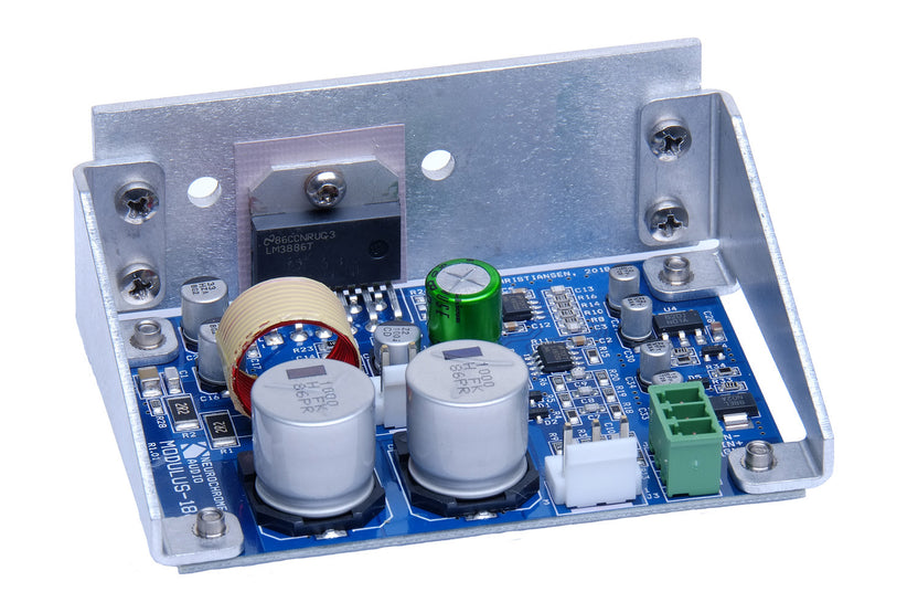
THD+N -107 dB 0.00045 % 40 W, 8 Ω, 1 kHz
The Neurochrome Modulus composite amplifier topology uses a precision amplifier to perform error correction on a less precise power amplifier. The Modulus-186 is a composite amplifier, which uses an LME49720 to perform error correction on an LM3886 power amplifier IC. This results in an amplifier which has the precision of the LME49720 and the power of the LM3886. This error correction is the central point of the Neurochrome Modulus composite architecture. The composite design will correct for many types of error, including distortion and power supply induced errors.
The error correction circuit in the Modulus-186 has its own regulated power supply. Consequently, the power supply for the error correction circuit is clean and free of ripple, even if there is some ripple voltage on the power supply to the board. In addition, the error correction circuit (LME49720 and associated components) has its own power supply rejection (the PSRR of the LME49720 due to its design and architecture). The end result is that the error correction circuit will correct for any distortion and supply-induced errors by the LM3886. This is done without introducing any errors of its own, while staying within the performance limitations of the LME49720. The end result is a powerful amplifier with vanishingly low distortion.
As mentioned, the error correction circuit also corrects for power supply induced errors in the power amplifier. This makes the Modulus-186 indifferent to the type of power supply used. When operated at levels below clipping, the Modulus-186 performs as well on a well regulated switching supply as it does on an unregulated power supply.
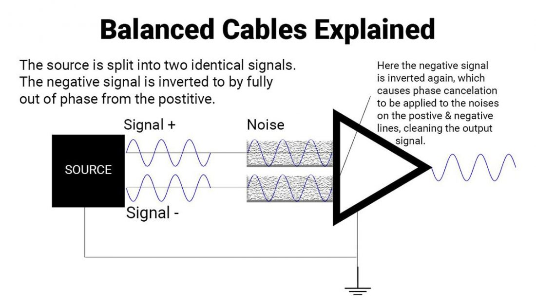
pseudo-differential cable between the single-ended (unbalanced, RCA) source and the differential (balanced, XLR) input on the Modulus-186. These cables can easily be made by the savvy DIYer. They are also available commercially.
The Modulus-186 has a differential (balanced, XLR) input. There are two reasons for this:
Using differential signalling moves the ground connection between the various pieces of equipment out of the signal path. This results in a reduction in mains hum of about 90 dB (31,600×), which is nearly as good as you would get from an input transformer (but without the distortion of the transformer).
- Differential signalling sounds better.
- Differential signalling measures better as it rejects hum.
From Tom's description.
Though Tom is the electrical engineer, I only go by what I read.
Though Tom is the electrical engineer, I only go by what I read.
It may have a balanced input through a balanced receiver IC (ie not natively balanced) but to be "fully balanced" a power amp must be bridge mode.
The important part is the differential input, and any op-amp input already has both inverting and non-inverting circuitry. Even if you have to add an extra transistor to an input stage, it is not an additional component in series with the signal path, but in parallel - yes, you have two transistors instead of one, but each only handles half the signal, so the total path length is no longer / more complicated than with unbalanced. The same applies to outputs.
I totally disagree and for all the reasons I gave the last time we "debated" just this for pages.
Please don't bother replying to this as lifes too short.... I refer you to everything I said last time.
And you are totally wrong, for all the reasons I gave the last time we "debated" just this for pages.
Please don't bother replying to this as lifes too short.... I refer you to everything I said last time.
That’s nice, perhaps you can find a bridge to connect Jez and julf!Both Si and myself run in bridged mode so we are sorted then
I find this interesting, coming as it does from this forum’s principal proponents of the ‘the science is settled, don’t argue with the physics’ viewpoint, usually on cable threads and the like.
It seems to me, the science may be settled, but there is no agreement as to where and how it has settled...
Every piece I had in my studio in 2012 came with XLR ins and outs apart from a couple of pieces of vintage stuff. Monitors, compressors, amps, desk, everything.This is getting on for half my lifetime ago so my memory is a bit fuzzy, but as I recall our studio was pretty much exclusively single-ended. We had a Soundcraft Spirit Studio 16/8/2 desk, the muti-track recorder was an Alesis ADAT (an early digital 8 track that recorded to a SVHS tape!) and a rack of outboard kit (digital reverbs, delays, compressors etc). I am certain all that lot was wired up with bog-standard mono 1/4” jack plugs, a right bloody rats nest to be honest. Its only recently I went through what was left of the cables that had been sitting in my cellar for ages and flung a bin-sack full of filthy junk out, and none were TRS jacks. I can remember the couple of XLRs we had were used one on the JP6 and the others were just mic leads!
Well I haven't read the previous exchange you're referring to, but surely if it was just a matter of semantics and pedantry, it wouldn't generate quite so much heat. It certainly appears as though there's a pretty fundamental difference of view between you, about matters technical. That's the interesting thing, because even if we accept the view that the science is 'settled', the engineering might not be.Nah it's just that Julf is CEO of "Pedant's R' Us!" and and was awarded a lifetime subscription to "Semantic's Weekly" magazine
Ah, interesting, thank you. That's plausible, but hardly explains the evident heat in the disagreement (perhaps Jez' participation is all the explanation we require, howeverAs far as I can tell, they're arguing over what the word 'balanced' means in the context of electrictronic signals.
). It doesn't invalidate my point, that if engineers aren't in agreement about implementation, especially of 'core' concepts like balanced operation, then perhaps they should wind their necks in a bit over other engineers' implementation of other technologies (and yes, there are plenty of real-life, honest-to-goodness engineers designing cables and support systems).
the chain seemed quieter with XLR. Not sure if there is any theory that stands up there
Yep that's exactly the purpose of balanced cables.
but it's the balanced amps themselves that are the important concept here, not the cables... in fact in some respects any old cable, not even screened, will do BECAUSE it's balanced.