advertisement


Avondale NCC300 amp project ..

I've been messing about, troubleshooting and experimenting. My bottom line impression is that "tweaking" is just a downhill slide from what is as perfect an amp experience as I've ever had. This is likely credit to both Les and his circuitry – Les for his experience and taste in design choices and the circuit for having such a solid grip on things that there's no need for compensation.

The one thing that might be worth the effort is the BD237 mounted to the heat spreader. It could be that gluing the 2N5551 to the heat spreader will accomplish the same thing. I'll give this a try on my first build and report.
 
Thanks Flash, much appreciated. The 2N5551 will be fine either glued to the heatsink
or, in the case of the 135 'shelf', perhaps a drilled hole to take it with a spot of thermal
paste.?
 
Looking sweet, Alan!
A couple component questions:
  1. Where do you get those little seats for the transistors? They look like a good idea at least for tweaking the offset with the BC546s.
Thanks
...I think the transistor seats are just spreaders - they don't allow you to pull and swap out transistors, just help make sure the legs are postioned correctly.
 
Over the weekend I fitted a separate PSU for the front end..top right. A 120va 42-0-42 transformer and a little PCB with a couple of 10000uf 80v caps fed by MBR20200 rectifiers, there is now no filters (L or R) used anywhere on the PSUs. I did have L on the miniCap6's but removed them and a smoother crisper presentation was the result. :)

26468680137_ef1424731e_h_d.jpg


The front end rail voltage with this new PSU (raw) is at 66v and the regs now supply 55v not the 50v as set originally. All is well but as a cautionary measure I dropped this to 52v. But I don't think theres any issue with this slightly higher supply voltage to the front end, all the components are 65v & 100v anyway.

26468679837_7d35fca09a_h_d.jpg


All tucked under the amp boards..checking the bias and a small tweak to bring it back to 2.2v. Its up and running in the workshop system for a few hours before I decant to the main system later today.
 
Last edited:
But I don't think theres any issue with this slightly higher supply voltage to the front end, all the components are +100v anyway.

Even the transistors?

I replaced the BC550s on my hackernap with 2SC2547Es because I an running 56V supplys

Pete
 
Even the transistors?

I replaced the BC550s on my hackernap with 2SC2547Es because I an running 56V supplys

Pete

Should of said,

reg have 2N5551 & 2n2401 which are 65v devices so I'm running it close but OK. The front end transistors ZTX753, 653 BC556 546 are 100v and 65v devices I recall so at 52v its all good.

It was in the workshop system for about 4 hours. Its now in my main system (1 hour)
and sounding as good as it gets IMO.

Graham
 
...I think the transistor seats are just spreaders - they don't allow you to pull and swap out transistors, just help make sure the legs are postioned correctly.

My recollection was that they were designed to easily reform the in-line pins of e-line transistors like the ZTX653/753 into the triangular format of the TO-18 devices.

You can get them here:

http://uk.farnell.com/multicomp/mpx05gfnb/transistor-pad/dp/519972?ost=519972&ddkey=http:en-GB/Element14_United_Kingdom/search
 
The 2N5551 will be fine either glued to the heatsink or, in the case of the 135 'shelf', perhaps a drilled hole to take it with a spot of thermal paste.?

Ah, I like the hole idea. Last night, I glued the 2N5551 to the top of the 135 shelf because that allowed access to the solder pads on the board. However, the shelf is so thick that the legs barely made the distance. A hole with the 2N5551 stuffed into it would provide excellent heat dissipation while also making for easy attachment of the legs to the solder pads.

But, alas, such holes drilled into the heat spreader require forethought, and at this point, the power transistors were all soldered up, so I'll live with it as is. In the end, I like attaching a BD237 via M3 bolt to a tapped hole, despite having to sort out the leg connections and hanging some components from the underside.
 
But is it sounding better than when the FE & output supplies were shared? ;)

Still early days (hours) but oh yes...its even more transparent with a delicacy that wasn't there before. (and before it was bloody good) Imagining is truly stunning with even more control and texture. Its clearly a notch up over the shared supplies.

As stated I think these might be my last amps...I'm very pleased with the results.
 
Here's the original patent for "transistor mounding pad":
Filed Oct. 5, 1959, Ser. No. 844,464 1 Claim. (Cl. 317-100) The present invention relates to a transistor mounting pad of the type which will maintain the transistor spaced from a circuit board to thereby prevent moisture entrapment between the base of the transistor and the circuit board.
There are various other claims of virtues, but none of them meet my original interest in providing a push fit connection for transistors.
 
Still early days (hours) but oh yes...its even more transparent with a delicacy that wasn't there before. (and before it was bloody good) Imagining is truly stunning with even more control and texture. Its clearly a notch up over the shared supplies.

Hard to imagine, but you've got me thinking how to fit a mini PSU for the front ends into the 135s. It'll require careful choices, but it looks possible!
 
Mine are making music and sounding superb Symbols and voice sound so natural and clear, bass and drum has impact and better definition
I know this will improve over the next week or so

20180409_185128 by Alan Towell, on Flickr

Alan
 
Great news Alan ..will be looking forward to reading some of your audio experiences. :)
Graham I agree with your findings these amps are pretty special;)
Congratulations Les I love them already, you have an excellent product here and wish you all the best with it
thank you very much for this opportunity to test this amplifier, im only running the Bias voltage at 2.1v whilst they are running in but I'm sure they are capable of more
Best
Alan
 
Should of said,

reg have 2N5551 & 2n2401 which are 65v devices so I'm running it close but OK. The front end transistors ZTX753, 653 BC556 546 are 100v and 65v devices I recall so at 52v its all good.

It was in the workshop system for about 4 hours. Its now in my main system (1 hour)
and sounding as good as it gets IMO.

Graham
Actually my FE transformer was from a hackenap amplifier group by and is 44-0-44V but only the input regs see the product of this in my case 65V but I set the regs at 45V with a 35-0-35V transformer first, Then I adjusted them up to 52-0-52 DCV with the voyager R Core front end transformers and I am also getting 51.8DCV from the output R core transformers so ballenced with the input
Also the first stage after the reg's only see the 52v DC

Alan
 
Here's the original patent for "transistor mounding pad":

There are various other claims of virtues, but none of them meet my original interest in providing a push fit connection for transistors.

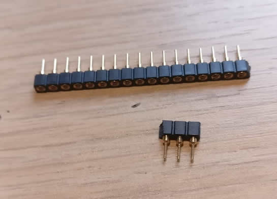
You need something like these
pin-terminals.jpg


I have tested inserting the legs of TO92s into them and they go in nice and firmly and can also be easily removed. You can break them off individually, so with a bit of fiddling you could fit them where a TO92 should go. I've just tested, and the spacing is such that two still joined will fit the diagonal two hole span of a standard TO92 PCB layout, so you can get away with a block of two plus a single one.

I don't know what they are called though. I have two strips of them as per the one pictured (enough for 13 TO92s), and you're welcome to them if you wish (PM me your address and I'll pop them in the post). Alternatively someone can probably provide a link to a supplier, I'm sure.


advertisement


Back
Top