advertisement


Two positive rails from HackerCap

Chops54

pfm Member
I've used a HackerCap board on several occasions when I've wanted two positive rails by reversing the diodes and caps on the negative side of the board. However a recent hum problem had me digging around and I realised that reversing these two diodes, whilst giving me two positive rails, only gives half wave rectification per rail even though I'm still using a centre tapped transformer. I've drawn the circuit out from the board so I can see that the rectifiers form the bridge across the two ac terminals. To remedy this I've removed the four diodes from the board and constructed two full wave bridges on thin strips of vero board and installed them upright at the front of the board. I just like someone to confirm that I'm on the right track with this.
I'll post a few pics later.
 
No, using 2 diodes, one from each end of a centre tapped transformer is the classic full wave rectifier circuit. Doing it twice, as I understand you to be doing doesn`t affect that.

You are saving one diode`s worth of voltage drop but the downside is that you are using the transformer in an unbalanced manner and so maximum safe current will be reduced.

A better solution, assuming your transformer allows, is to split the two windings and use two separate bridge rectifiers.
 
Hi Barry, yes I understand the classic full wave rectifier circuit using the centre tap but the HackerCap board doesn't appear to work like that. I've just finished building two full wave bridges and yes I've split the two windings.
 
Simon
I am using a hacker cap in the same configuration as you in my 821 pre amp to provide 2 positive supplies, and I dont get any hum?.
2 diodes is still full wave rectification, half wave is a single diode.

Alan
 
Chops, full wave will give you smoother DC, notionally. The peaks are the same height, just closer together and hence lower RMS with full wave.

All else being equal I'd go full wave with a centre tap, and have a common mode choke on each rail if there's space.

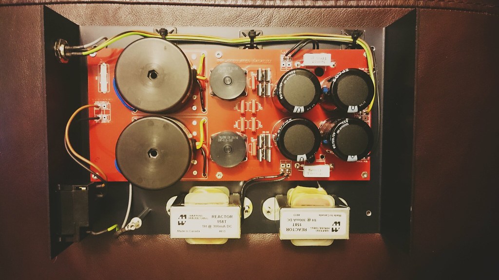
17163065813_c4b29df84f_b.jpg


This is one channel's worth of Paradise PSU, there's a bipolar shunt reg locally as well.
 
Hi Alan, I can understand how the HackerCap works in normal pos/neg dual rail mode but I can't understand how you can still have full wave rectification after turning two diodes around on one side. Only one half of the secondary winding is now being used for each rail and the voltage doesn't swing either side of the centre tap or am I missing something?

Si, I read through your Paradise build thread and very good it was too but it's out of my league I'm afraid. I take my hat off to you mate but when I realise how many of these things you've built well what can I say. I really do struggle to get my head around some of this stuff.
 
Hi Simon,
After drawing it out myself I see what you mean from a centre tapped transformer :eek:
Mine has twin secondarys

Alan
 
Yes I have the build manual thanks.

I think I've been looking at the drawing all wrong Alan. I assumed that the four diodes made a bridge but they're not implemented this way. It took me a while but looking at my drawing and taking one rail at a time we have a centre tapped transformer ( or dual winding ) with a diode fed from each end and the centre tap as zero which is the classic full wave rectifier circuit. The other rail shares the same centre tapped winding but has it's own diodes etc ie the two rails are in parallel with a common zero volt rail. Hopefully I'm on the right track with this at last.
 
2 positive rails is no problem. Let's call the standard positive rail Rail1 and the standard negative rail Rail2. You just need to do 2 things:

* Put the diodes in backwards on Rail2
* Reverse the polarity of the capacitors on Rail2.
* Everything on Rail1 stays the same.

Edit: you can create a centre-tapped secondary from two regular secondaries like this (ignore the voltages, I just swiped the first applicable image from Google):

trans64.gif


Hope that helps,
Carl
 
Yes, thanks for that Carl. It wasn't the transformer that caused the issue for me, rather the implementation of the diodes. I've worked it out now and all's well.


advertisement


Back
Top