James
Lord of the Erg\o/s
Design Brief
The E-IX was designed to look like Linn Kan or LS3/5a from the front but sound better than either. It features the world's best (IMO) 5.25” mid-woofer in acoustic suspension that is seamlessly mated with a 1” tweeter via an acoustic Linkwitz-Riley 4th order crossover network. There was originally a choice of configuring the crossover for either boundary (wall mount) or free space location, but I’ve decided that the wall-mount version is superior and more likely to be successful for UK rooms. This set of instructions is for the wall-mount version.
Construction is straightforward. The E-IX uses hardwood timbers for its cabinetry and MDF for its baffle. Intending owners can choose between flush mounted and exposed drivers or a recessed and grilled baffle.
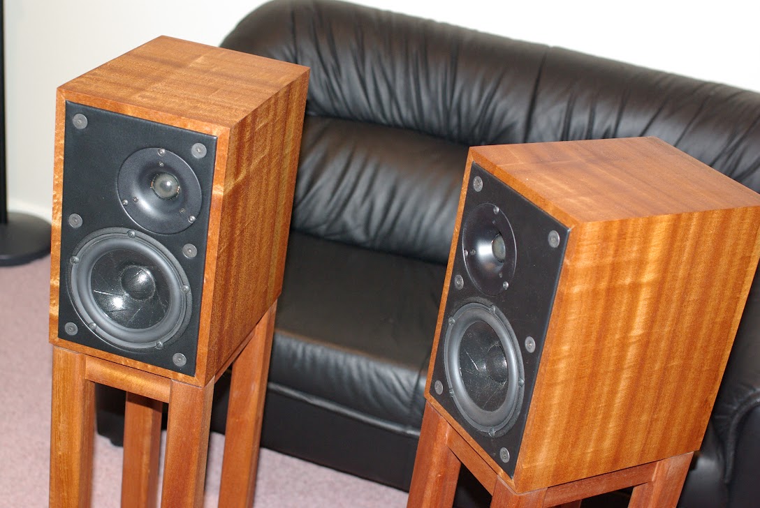
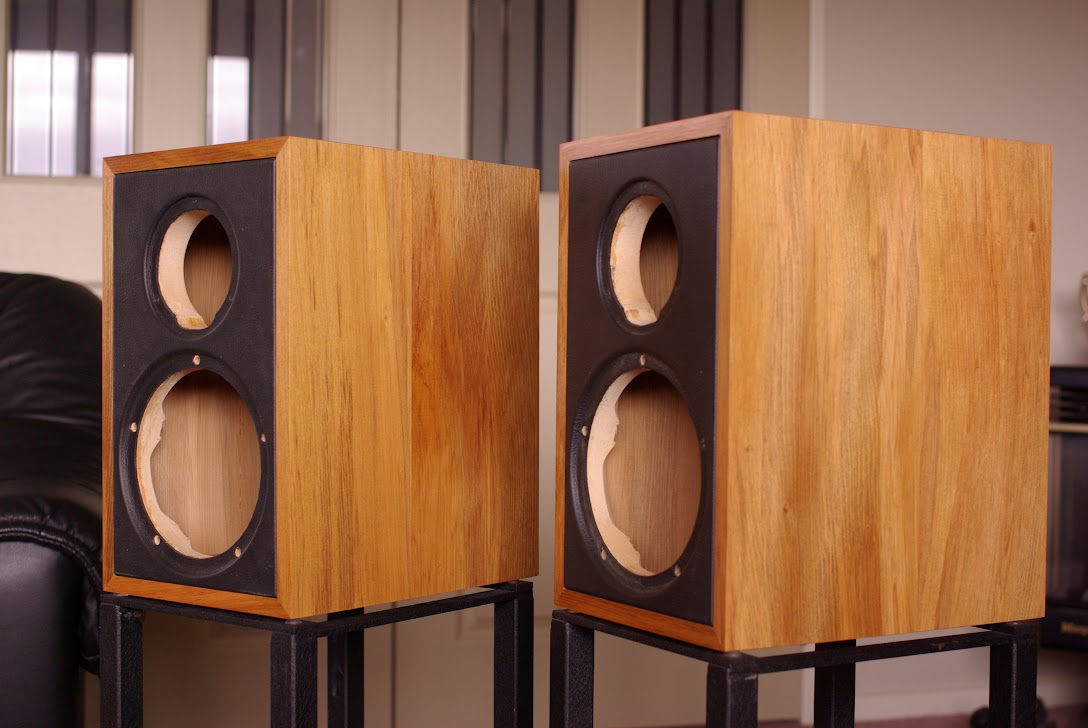
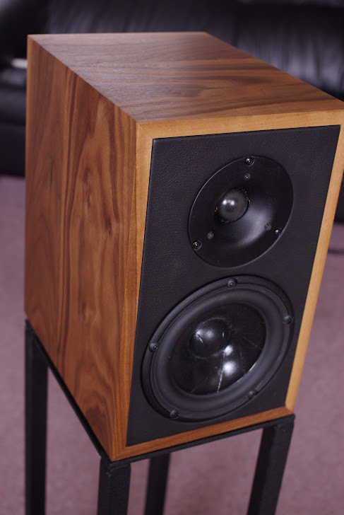
Here is an original pair in Sapele with offset tweeter and grille-less baffle.
Depending on chosen configuration and room conditions, the E-IX is generally good for a genuine 50 Hz to 18 kHz. With the benefit of appropriate room gain and suitable amplification, it will have little difficulty reproducing the lowest fundamental note of a bass guitar at moderate volume. However, as it has a sensitivity of only 84dB/2.83V/m, it won’t like being asked to replay AC/DC at realistic levels. In a typically compact room, the E-IX should do justice to virtually all kinds of music.
Bill of Materials (per side)
Cabinetry
• 1.5m of hardwood at least 270mm wide or 3.0m 135mm wide (for jointing). Choose kiln-dried, quarter-sawn and reasonably hard but workable timbers. Great results can be had with American Black Walnut, Sapele, Oak and Cherry.
• 300x180mm MDF. 18mm for grilled version, 25mm for grille-less version.
• 300x180mm MDF 6mm for grille frame (grilled version only)
• 350x230mm upholstery grade leather (exposed version only)
• 12x M8 countersunk bolts
Drivers
• Scan-speak 15W8530-K01 Revelator
• Morel CAT378 or MDT37
Crossover
• 1.0mH inductor (Jantzen 15AWG P-Core Part Num 5383)
• 0.27mH inductor (Jantzen 18AWG Air-Core Part Num 1635)
• 18.0uF capacitor (Jantzen Z-Standard)
• 3.3uF capacitor (Jantzen Z-Superior)
• 2.7uF capacitor (Jantzen Z-Standard)
• 4R7 resistor (Jantzen 10W MOX RSS5%)
• 7R5 resistor (Jantzen 10W MOX RSS5%)
Ignore the value of 2.7uF on this photo. The correct value for the Z-Superior cap is 3.3uF.
Miscellaneous
• Terminals (4mm sockets or Neutrik Speakon)
• Wiring (multi-strand, around 14AWG for mid-woofer and 18AWG for tweeter)
• Fibreglass insulation batting
• 5x M5 25mm cap screws or button head bolts
• 3x 18mm 7g wood screws
• Contact adhesive (for affixing leather or grille cloth)
• High quality wood glue
• Biscuits (optional but highly recommended)
Construction of cabinet (per side)
Caveat: It is assumed you understand woodwork and are proficient in the use of the right tools. I cannot accept any liability for loss or damage to your person or possessions in following these instructions. The integrity of the build is vital to the finished cosmetic and acoustic results. Take shortcuts at your risk.
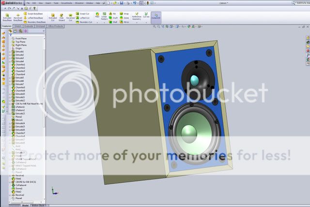
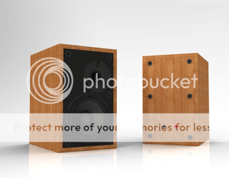
The cabinet front and side elevation are detailed in the following picture:
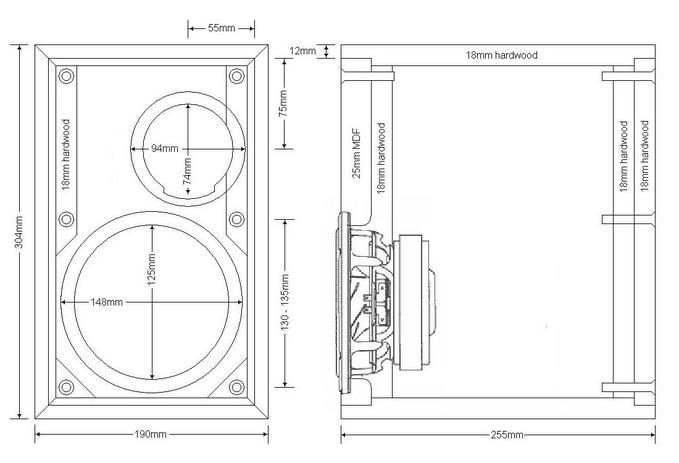
If building the asymmetrical tweeter version, you'll need to prepare a left and right baffle each.
Preparation of hardwood timbers – machine or plane the boards flat to a thickness of 18mm. If full width boards are not available, joint first then plane to desired thickness. Rip boards to 256mm width with one edge planed straight and square. Measure and cut a length to around 1,050mm. You’ll need to produce 988mm of mitre-cut boards from this length. The extra timber is for insurance against tears. A sharp and accurate saw is vital.
Cut a 6mm deep and 26mm wide rebate on the planed edge of the metre-long board. Cut a similarly deep (6mm) rebate on the unfinished edge (same side) so that there is 211mm of un-rebated width on the board. If your board was exactly 256mm wide, the second rebate should be 19mm wide. The idea here is that there is 26mm + 211mm + 18mm to make up the 255mm finished depth of the E-IX. The extra 1mm of waste is to allow the rear edge to be trimmed flush with the back with a bearing guided router.
This should leave 12mm of exposed edge, which ‘frames’ the baffle and back. Mitre cut two lengths each at 190mm and 304mm. These boards form the top/bottom and sides respectively. If the boards are cut from a contiguous piece (i.e. cut in order of bottom, left, top, right), then highly figured grain will wrap all the way around for a delightful finish.
Set aside the leftover board for the back, which will need to be rough cut to 280x166mm. Leave this until the cabinet is assembled.
Cut biscuit (size 20) slots into the mitres, taking care to check cutting depth against available material to avoid break through. Each joint should have only two biscuits, which serve two purposes. Firstly, they strengthen the joint. Secondly, they maintain joint alignment when gluing up and clamping. Test fit the panels with dry biscuits. If the board was perfectly flat, cut square and perfectly mitred at 45 degrees, they should fit nicely.

A technique to ensure perfectly square assembly and gluing is to cut a couple of MDF (18mm) boards to fit the rebated space snugly.
If the panels have been correctly dimensioned to spec, these boards should measure exactly 280x166mm, but with the corners trimmed to allow glue seepage. With these boards and biscuits in place, gluing up and clamping will be a lot easier. They are removed once the glue has set. Excess glue must then be trimmed away to enable the fillets to be secured into place. These hardwood fillets are roughly 18x18mm square and obtained from off-cuts. Make sure they are oriented so that the M8 threads can be cut for maximum purchase and not split the fillets. These fillets are simply glued on flush with inner edge of the rebate, as per diagram (take care with woofer cut-out). The rear part of the cabinet is filleted similarly, but without woofer cut-out). Fillets should NOT be mitre cut but butt jointed instead to enable the corner M8 bolts to be symmetrically oriented front and back.
Back panel
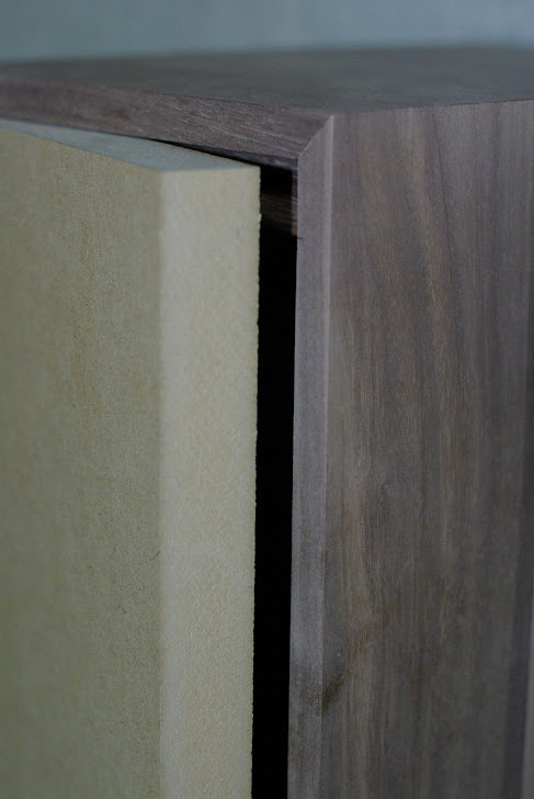
The back panel should be sized to allow a 1mm gap when inset into the cabinet. If the rebated space is exactly 280x166mm, then the back panel should be trimmed to 278x164mm. It does not matter if this is slightly more or less, but aesthetically the gap should be small and even all around. The purpose of this gap is to allow the timber some lateral movement. If the back panel is constructed from man-made materials (e.g. MDF) then it can be cut to fit snugly. To allow space for the gasket to compress, cut a 6mm rebate to a depth of 1mm on the inside face of the back panel. This will be lined with self-adhesive neoprene weather seal.
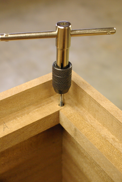
Mark on the back panel where bolt holes will be drilled. Wedge the correctly sized back panel into position (for even gap) and drill 7.0mm holes all the way through the fillets. Enlarge the 7.0mm holes on the back panel to 8.5mm and counter sink to a depth that enables the M8 bolts to be flush with the surface. A drill press helps immensely with perfectly perpendicular holes and controlled depth of cut with precise repeatability. The threads in the 7.0mm holes in the fillets are then cut carefully with an M8 tap.
Bolt up the back panel and trim the rear edge of the cabinet flush with a bearing guided router bit or with a random orbital sander. Beware of tearing edges. The back panel is now ready to be drilled to accept your choice of electrical terminations.
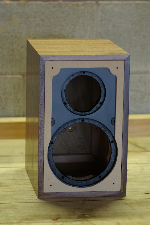
Front baffle
There are two choices to be made. First is whether grilles or naked drivers are preferred. Second is whether offset tweeter is likely to be useful in your listening environment. The purist version is offset tweeter and naked drivers. Offsetting the tweeter enables them to be placed on the outside to improve alignment with the woofer, or inside to change secondary reflections from side walls. I haven’t compared all four configurations so I can’t make any statements about how different they will sound. But if there are any differences, they are going to be far less than the differences in how the same pair will sound in different rooms.
The naked drivers baffle will be cut from 25mm MDF, which is covered with leather (1-1.5mm thick). The grilled version will be cut from 18mm MDF, painted and covered with a 6mm grill. Both versions can be bolted with M8 bolts as per the back panel, or they can be glued into place for a cleaner look.
The driver cut-outs should be cut with a router mounted on a circle cutting jig. It’s easier to cut the rebate to the correct depth with an 18/19mm straight cutter first, and then the hole is cut after that. For a leathered/grille-less baffle, the rebate will need to be cut 1.5-2mm wider to allow the leather to tuck under the driver frame; but there is no need to cut any deeper than depth of the driver flange.
When the rebate and hole have been cut, test fit your drivers. At this stage, I also recommend you drill the holes for the driver fasteners. The mid-woofer is secured with five M5 bolts (I don’t recommend wood screws) into T-nuts. The tweeter is secured with three wood screws (you could also use M4 bolts and T-nuts, but beware of cracking the plastic flange).
For a neat finish and minimal air-flow restriction, I recommend scalloping the rear of the cut-out. Do this after the driver bolt/T-nut positions have been drilled.
The baffles should be test-fitted onto the cabinet shell, and the holes for the M8 bolts (if desired) should be drilled/tapped/countersunk as per the back panel.
For the grille-less baffle, I recommend a natural leather hide finish. Use furniture-grade leather and not shoe leather. It should be around 1.0-1.5mm thick, soft and pliable. You won’t need an entire hide; off-cuts from your local upholsterer should be plenty. A small 2mm rebate should be cut into the side of the baffle for the leather to tuck into as well; otherwise the baffle will NOT fit the cabinet shell.
Affix the leather to the finished baffle with contact adhesive (follow the instructions on the tin) and give it a slight stretch to avoid wrinkles. The leather should be tucked over each edge (2mm rebate) and glued securely, then trimmed. Use a rolling pin to force a tight bond. The leather serves to seal the drivers and give the Ergo a touch of class.
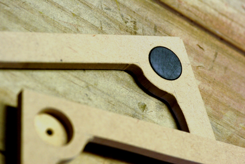
For the grilled baffle, the tweeter will have to be centrally mounted (no plans, unfortunately but you should be able to figure this out by aiming for a 7-10mm gap between woofer and tweeter flanges). The grille-less baffle is cut from 18mm MDF is almost identical fashion. The grille itself is cut from 6mm MDF and held in place with button magnets that line up with the 8mm bolts (clever, huh?).
The frame is simply covered with acoustically transparent fabric in a colour of your choice.
Home run
At this stage, your cabinets should be ready for final sanding and finishing. I prefer Danish Oil, but you can choose any finish you like. Just remember to sand off all imperfections first.
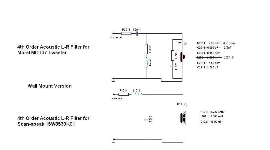
While the finish is curing and hardening, the XO boards can be prepared. I simply used a couple of pieces of 6mm MDF cut to roughly 150mm x 100mm. The XO components are mounted with cable ties and hardwired. At some stage, if there is demand, I may get some PCB boards made. Here is the layout and schematic.
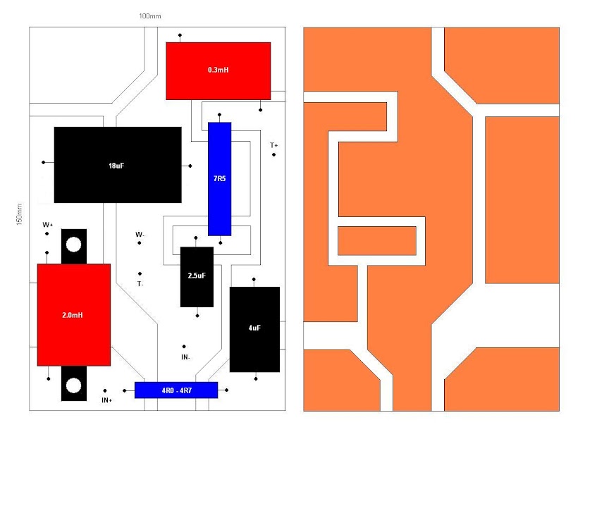
Two 15R resistors may be used in parallel to obtain 7R5. Jantzen has 7R5 resistors, so doubling up is not always necessary.
I recommend affixing the XO board onto the rear panel, over the input terminals for a neat look. Another worthwhile option is to outboard the XO in a separate case. This is what I have done with mine.
Almost there now … all that remains is to stuff the cabinet, wire up and install the drivers.
I really like fibreglass insulation batts, but I guess Dacron could also do the job. This is where experimentation can pay dividends (and why I engineered removable fronts and backs). In my room, I find 100% fill to sound best. This means the batts fill up all the space, but not under tight compression.
Solder the driver terminals to the respective wires. Note the common ground that is shared with both drivers and XO board, which is connected directly to the negative input terminal. Both drivers are then fastened into place.
If the build has gone smoothly, your E-IXs are now ready to place some tunes. I find that they work best on rigid stands. I’ve had good results on an ES-11 type stand.
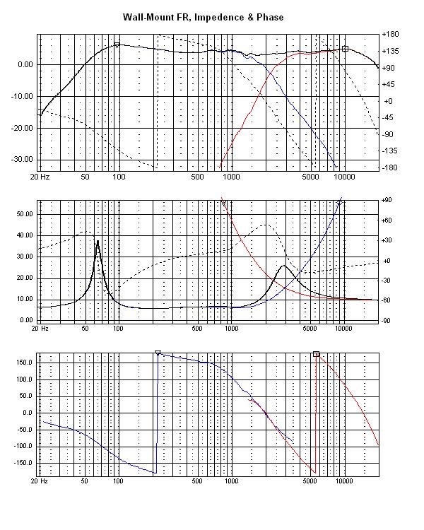
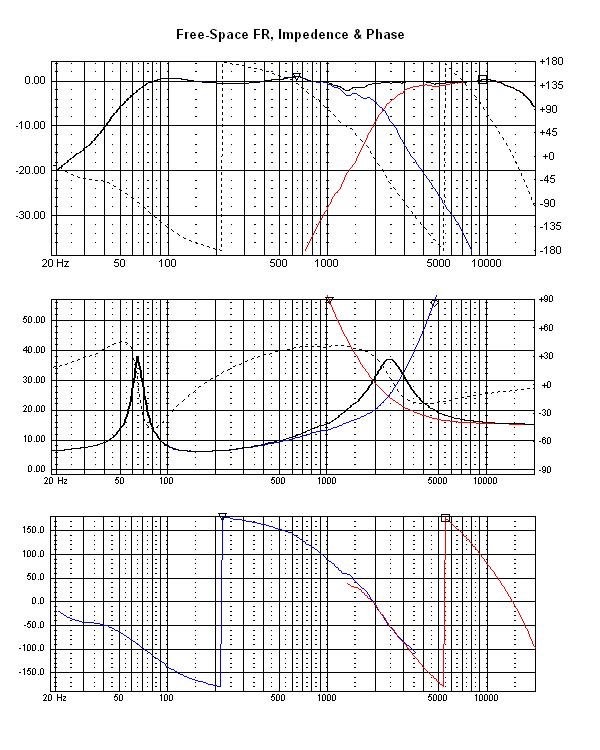
Here is the FR, impedance and phase charts for both wall-mount and free-space versions.
Good luck with your project and please start a thread in the DIY room if you want to document your Ergo adventure or wish to ask me any questions.
James
The E-IX was designed to look like Linn Kan or LS3/5a from the front but sound better than either. It features the world's best (IMO) 5.25” mid-woofer in acoustic suspension that is seamlessly mated with a 1” tweeter via an acoustic Linkwitz-Riley 4th order crossover network. There was originally a choice of configuring the crossover for either boundary (wall mount) or free space location, but I’ve decided that the wall-mount version is superior and more likely to be successful for UK rooms. This set of instructions is for the wall-mount version.
Construction is straightforward. The E-IX uses hardwood timbers for its cabinetry and MDF for its baffle. Intending owners can choose between flush mounted and exposed drivers or a recessed and grilled baffle.
Here is an original pair in Sapele with offset tweeter and grille-less baffle.
Depending on chosen configuration and room conditions, the E-IX is generally good for a genuine 50 Hz to 18 kHz. With the benefit of appropriate room gain and suitable amplification, it will have little difficulty reproducing the lowest fundamental note of a bass guitar at moderate volume. However, as it has a sensitivity of only 84dB/2.83V/m, it won’t like being asked to replay AC/DC at realistic levels. In a typically compact room, the E-IX should do justice to virtually all kinds of music.
Bill of Materials (per side)
Cabinetry
• 1.5m of hardwood at least 270mm wide or 3.0m 135mm wide (for jointing). Choose kiln-dried, quarter-sawn and reasonably hard but workable timbers. Great results can be had with American Black Walnut, Sapele, Oak and Cherry.
• 300x180mm MDF. 18mm for grilled version, 25mm for grille-less version.
• 300x180mm MDF 6mm for grille frame (grilled version only)
• 350x230mm upholstery grade leather (exposed version only)
• 12x M8 countersunk bolts
Drivers
• Scan-speak 15W8530-K01 Revelator
• Morel CAT378 or MDT37
Crossover
• 1.0mH inductor (Jantzen 15AWG P-Core Part Num 5383)
• 0.27mH inductor (Jantzen 18AWG Air-Core Part Num 1635)
• 18.0uF capacitor (Jantzen Z-Standard)
• 3.3uF capacitor (Jantzen Z-Superior)
• 2.7uF capacitor (Jantzen Z-Standard)
• 4R7 resistor (Jantzen 10W MOX RSS5%)
• 7R5 resistor (Jantzen 10W MOX RSS5%)
Ignore the value of 2.7uF on this photo. The correct value for the Z-Superior cap is 3.3uF.
Miscellaneous
• Terminals (4mm sockets or Neutrik Speakon)
• Wiring (multi-strand, around 14AWG for mid-woofer and 18AWG for tweeter)
• Fibreglass insulation batting
• 5x M5 25mm cap screws or button head bolts
• 3x 18mm 7g wood screws
• Contact adhesive (for affixing leather or grille cloth)
• High quality wood glue
• Biscuits (optional but highly recommended)
Construction of cabinet (per side)
Caveat: It is assumed you understand woodwork and are proficient in the use of the right tools. I cannot accept any liability for loss or damage to your person or possessions in following these instructions. The integrity of the build is vital to the finished cosmetic and acoustic results. Take shortcuts at your risk.
The cabinet front and side elevation are detailed in the following picture:
If building the asymmetrical tweeter version, you'll need to prepare a left and right baffle each.
Preparation of hardwood timbers – machine or plane the boards flat to a thickness of 18mm. If full width boards are not available, joint first then plane to desired thickness. Rip boards to 256mm width with one edge planed straight and square. Measure and cut a length to around 1,050mm. You’ll need to produce 988mm of mitre-cut boards from this length. The extra timber is for insurance against tears. A sharp and accurate saw is vital.
Cut a 6mm deep and 26mm wide rebate on the planed edge of the metre-long board. Cut a similarly deep (6mm) rebate on the unfinished edge (same side) so that there is 211mm of un-rebated width on the board. If your board was exactly 256mm wide, the second rebate should be 19mm wide. The idea here is that there is 26mm + 211mm + 18mm to make up the 255mm finished depth of the E-IX. The extra 1mm of waste is to allow the rear edge to be trimmed flush with the back with a bearing guided router.
This should leave 12mm of exposed edge, which ‘frames’ the baffle and back. Mitre cut two lengths each at 190mm and 304mm. These boards form the top/bottom and sides respectively. If the boards are cut from a contiguous piece (i.e. cut in order of bottom, left, top, right), then highly figured grain will wrap all the way around for a delightful finish.
Set aside the leftover board for the back, which will need to be rough cut to 280x166mm. Leave this until the cabinet is assembled.
Cut biscuit (size 20) slots into the mitres, taking care to check cutting depth against available material to avoid break through. Each joint should have only two biscuits, which serve two purposes. Firstly, they strengthen the joint. Secondly, they maintain joint alignment when gluing up and clamping. Test fit the panels with dry biscuits. If the board was perfectly flat, cut square and perfectly mitred at 45 degrees, they should fit nicely.
A technique to ensure perfectly square assembly and gluing is to cut a couple of MDF (18mm) boards to fit the rebated space snugly.
If the panels have been correctly dimensioned to spec, these boards should measure exactly 280x166mm, but with the corners trimmed to allow glue seepage. With these boards and biscuits in place, gluing up and clamping will be a lot easier. They are removed once the glue has set. Excess glue must then be trimmed away to enable the fillets to be secured into place. These hardwood fillets are roughly 18x18mm square and obtained from off-cuts. Make sure they are oriented so that the M8 threads can be cut for maximum purchase and not split the fillets. These fillets are simply glued on flush with inner edge of the rebate, as per diagram (take care with woofer cut-out). The rear part of the cabinet is filleted similarly, but without woofer cut-out). Fillets should NOT be mitre cut but butt jointed instead to enable the corner M8 bolts to be symmetrically oriented front and back.
Back panel
The back panel should be sized to allow a 1mm gap when inset into the cabinet. If the rebated space is exactly 280x166mm, then the back panel should be trimmed to 278x164mm. It does not matter if this is slightly more or less, but aesthetically the gap should be small and even all around. The purpose of this gap is to allow the timber some lateral movement. If the back panel is constructed from man-made materials (e.g. MDF) then it can be cut to fit snugly. To allow space for the gasket to compress, cut a 6mm rebate to a depth of 1mm on the inside face of the back panel. This will be lined with self-adhesive neoprene weather seal.
Mark on the back panel where bolt holes will be drilled. Wedge the correctly sized back panel into position (for even gap) and drill 7.0mm holes all the way through the fillets. Enlarge the 7.0mm holes on the back panel to 8.5mm and counter sink to a depth that enables the M8 bolts to be flush with the surface. A drill press helps immensely with perfectly perpendicular holes and controlled depth of cut with precise repeatability. The threads in the 7.0mm holes in the fillets are then cut carefully with an M8 tap.
Bolt up the back panel and trim the rear edge of the cabinet flush with a bearing guided router bit or with a random orbital sander. Beware of tearing edges. The back panel is now ready to be drilled to accept your choice of electrical terminations.
Front baffle
There are two choices to be made. First is whether grilles or naked drivers are preferred. Second is whether offset tweeter is likely to be useful in your listening environment. The purist version is offset tweeter and naked drivers. Offsetting the tweeter enables them to be placed on the outside to improve alignment with the woofer, or inside to change secondary reflections from side walls. I haven’t compared all four configurations so I can’t make any statements about how different they will sound. But if there are any differences, they are going to be far less than the differences in how the same pair will sound in different rooms.
The naked drivers baffle will be cut from 25mm MDF, which is covered with leather (1-1.5mm thick). The grilled version will be cut from 18mm MDF, painted and covered with a 6mm grill. Both versions can be bolted with M8 bolts as per the back panel, or they can be glued into place for a cleaner look.
The driver cut-outs should be cut with a router mounted on a circle cutting jig. It’s easier to cut the rebate to the correct depth with an 18/19mm straight cutter first, and then the hole is cut after that. For a leathered/grille-less baffle, the rebate will need to be cut 1.5-2mm wider to allow the leather to tuck under the driver frame; but there is no need to cut any deeper than depth of the driver flange.
When the rebate and hole have been cut, test fit your drivers. At this stage, I also recommend you drill the holes for the driver fasteners. The mid-woofer is secured with five M5 bolts (I don’t recommend wood screws) into T-nuts. The tweeter is secured with three wood screws (you could also use M4 bolts and T-nuts, but beware of cracking the plastic flange).
For a neat finish and minimal air-flow restriction, I recommend scalloping the rear of the cut-out. Do this after the driver bolt/T-nut positions have been drilled.
The baffles should be test-fitted onto the cabinet shell, and the holes for the M8 bolts (if desired) should be drilled/tapped/countersunk as per the back panel.
For the grille-less baffle, I recommend a natural leather hide finish. Use furniture-grade leather and not shoe leather. It should be around 1.0-1.5mm thick, soft and pliable. You won’t need an entire hide; off-cuts from your local upholsterer should be plenty. A small 2mm rebate should be cut into the side of the baffle for the leather to tuck into as well; otherwise the baffle will NOT fit the cabinet shell.
Affix the leather to the finished baffle with contact adhesive (follow the instructions on the tin) and give it a slight stretch to avoid wrinkles. The leather should be tucked over each edge (2mm rebate) and glued securely, then trimmed. Use a rolling pin to force a tight bond. The leather serves to seal the drivers and give the Ergo a touch of class.
For the grilled baffle, the tweeter will have to be centrally mounted (no plans, unfortunately but you should be able to figure this out by aiming for a 7-10mm gap between woofer and tweeter flanges). The grille-less baffle is cut from 18mm MDF is almost identical fashion. The grille itself is cut from 6mm MDF and held in place with button magnets that line up with the 8mm bolts (clever, huh?).
The frame is simply covered with acoustically transparent fabric in a colour of your choice.
Home run
At this stage, your cabinets should be ready for final sanding and finishing. I prefer Danish Oil, but you can choose any finish you like. Just remember to sand off all imperfections first.
While the finish is curing and hardening, the XO boards can be prepared. I simply used a couple of pieces of 6mm MDF cut to roughly 150mm x 100mm. The XO components are mounted with cable ties and hardwired. At some stage, if there is demand, I may get some PCB boards made. Here is the layout and schematic.
Two 15R resistors may be used in parallel to obtain 7R5. Jantzen has 7R5 resistors, so doubling up is not always necessary.
I recommend affixing the XO board onto the rear panel, over the input terminals for a neat look. Another worthwhile option is to outboard the XO in a separate case. This is what I have done with mine.
Almost there now … all that remains is to stuff the cabinet, wire up and install the drivers.
I really like fibreglass insulation batts, but I guess Dacron could also do the job. This is where experimentation can pay dividends (and why I engineered removable fronts and backs). In my room, I find 100% fill to sound best. This means the batts fill up all the space, but not under tight compression.
Solder the driver terminals to the respective wires. Note the common ground that is shared with both drivers and XO board, which is connected directly to the negative input terminal. Both drivers are then fastened into place.
If the build has gone smoothly, your E-IXs are now ready to place some tunes. I find that they work best on rigid stands. I’ve had good results on an ES-11 type stand.
Here is the FR, impedance and phase charts for both wall-mount and free-space versions.
Good luck with your project and please start a thread in the DIY room if you want to document your Ergo adventure or wish to ask me any questions.
James
Last edited:
")