
You are using an out of date browser. It may not display this or other websites correctly.
You should upgrade or use an alternative browser.
You should upgrade or use an alternative browser.
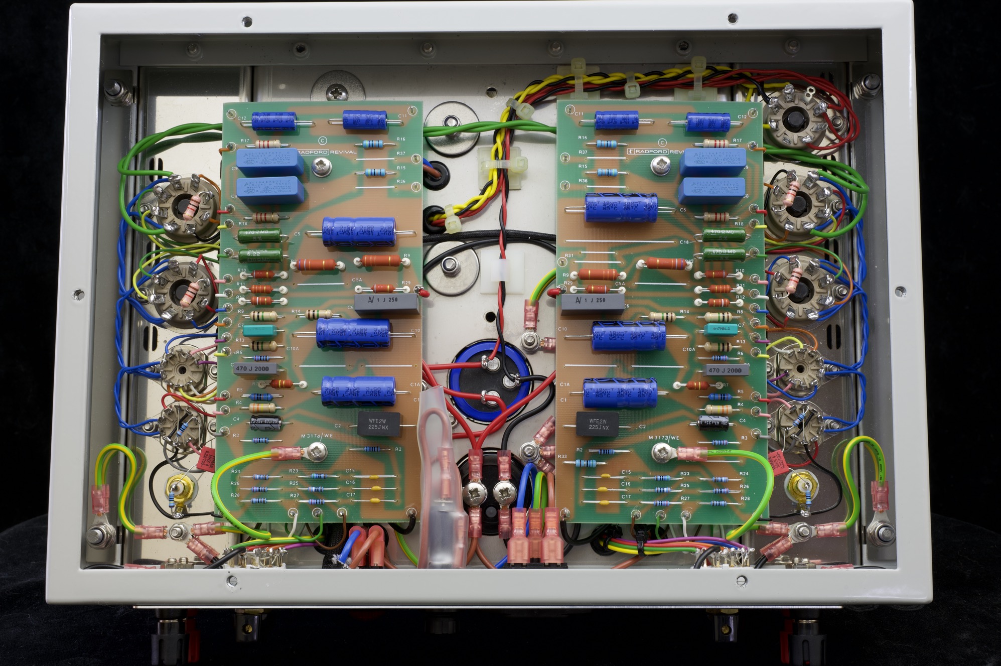
STA15 component layout diagram
- Thread starter Mike P
- Start date
Radford Revival
Trade: Radford Revival
A new one but it's the same:
chiily
PFM Special Builder
I did this one a while ago for a series 3.
 Boards with labels by Garf Arf, on Flickr
This board is the one without the resistor between audio gnd and earth. Just looked it up R33 is the johnny...
Boards with labels by Garf Arf, on FlickrThis board is the one without the resistor between audio gnd and earth. Just looked it up R33 is the johnny...
chiily
PFM Special Builder
Will, is there a conscious decision why the the film bypass caps aren't fitted on this one? I'm just curious....A new one but it's the same:
wd40addict
pfm Member
I upped my cathode resistors from 390R back to 470R to reduce strain on the EL34s. Presumably Radford went the other way back in the day when Mullards were freely available.
Radford Revival
Trade: Radford Revival
Will, is there a conscious decision why the the film bypass caps aren't fitted on this one? I'm just curious....
I stopped populating them years ago - these boards are 1:1 copies of the Woodside STA15/25 replacement boards which have provisions for them.
Basically an electrolytic has a far lower ESR than a 33k / 39k anode resistor!
It's a series 3 that I'm working on.
So far I've discovered that R19 and R20 are 390R on both channels and not 470R and that R32 has drifted up to c75K.
390R is correct, I just fit 470R to run things a little cooler.
Radford Revival
Trade: Radford Revival
Will, how much is a pair of populated replacement STA15 boards? The boards on this amp are quite scorched with a couple of lifting traces.
£200 fully populated cleaned / defluxed etc
Mike P
Trade: Pickwell Audio
Thanks, I'll ask the owner.£200 fully populated cleaned / defluxed etc