
You are using an out of date browser. It may not display this or other websites correctly.
You should upgrade or use an alternative browser.
You should upgrade or use an alternative browser.
regulator booster
- Thread starter teddy_pardo
- Start date
mikesnowdon
resU deretsigeR
Really?
I'll have to check mine then.
I'll have to check mine then.
mikesnowdon
resU deretsigeR
Yep,
Mine are Motorola so wrong. Isnt it weird that the regs still work, and definitely sound better?
Can anyone explain why?
Mine are Motorola so wrong. Isnt it weird that the regs still work, and definitely sound better?
Can anyone explain why?
mikesnowdon
resU deretsigeR
Calling all experts ( I know your looking in ") ) we are confused and need your help!!!
) we are confused and need your help!!!
) we are confused and need your help!!!mikesnowdon
resU deretsigeR
Ok, so were both using the C version so we need to flip our's around. Thats that cleared up then. Thanks Does running a transistor the wrong way damage it?
Im still curious as to how mine still work ok despite the transistor being back to front. WTF indeed!
Does running a transistor the wrong way damage it?Im still curious as to how mine still work ok despite the transistor being back to front. WTF indeed!
Does running a transistor the wrong way damage it?
I don't know, but as they are only pence each I would be inclined to replace them.
mikesnowdon
resU deretsigeR
Having the transistor orientated with the input voltage to the emitter like I have is referred to as the 'common-base' configuration. Apparently it's use where low input impedance is required, but suffers from high output impedance. Im not entirely sure how this applies to the superreg circuit, or how it still sounds better than the standard 7805. Maybe I'm hearing the benefit of basic RC filtering. What I do know is that its doing no harm and the transistor shouldn't be damaged in any way.
I wonder if any of the more knowledgeable members have any thoughts on this?
It will be interesting to compare how it sounds connected the right way. I wish I had some sim software (and knew how to use it) to make some waveform/distortion comparisons between the two configurations.
I wonder if any of the more knowledgeable members have any thoughts on this?
It will be interesting to compare how it sounds connected the right way. I wish I had some sim software (and knew how to use it) to make some waveform/distortion comparisons between the two configurations.
mikesnowdon
resU deretsigeR
I don't know, but as they are only pence each I would be inclined to replace them.
Missed your post as I was writing mine above. I think the transistors will be fine
EDIT: This thread is the 11th most viewed thread (out of hundred's/thousands) in the DIY section!
Mike. I think you might want to shoot me. I should not drink so much wine on a Friday night. The info I posted earlier was based on what I saw. I have just read it again and you read the pin outs from the bottom with the pins facing you, not from above!!
http://i73.photobucket.com/albums/i239/saxonsex/image001-9.gif
http://i73.photobucket.com/albums/i239/saxonsex/image001-9.gif
herewegoagain
Member
Well according to what I have read 547C means the I have mine the wrong way round. Looking at the top with the flat surface to the front and the dished facing towards you, the pin out is CBE, a B suffix is EBC and an A suffix is ECB. WTF!
Are you sure about this?
I have never known this to be the case - a TO92 package (like these 547's) should always have the same lead-outs - irrespective of the gain classification of the transistor!
mikesnowdon
resU deretsigeR
When I was looking at 'common base' configurations I read that this gives a minus gain. So you get less out than you put in. I also read somewhere that the common base setup is good for HF isolation. However this was in amplifier terms so I don't know if it has anything to do with this circuit.
Sure would be nice to do some sim's on this, common base might be a better way of doing it.
Sure would be nice to do some sim's on this, common base might be a better way of doing it.
Well it looks like you had it right all along?!
http://www.datasheetcatalog.org/datasheet/motorola/BC546B.pdf
http://www.datasheetcatalog.org/datasheet/motorola/BC546B.pdf
herewegoagain
Member
See post 91
What sort of reading are you supposed to get when using the hFE feature on a DMM? If I insert it the way I think it should go it reads 507 and the other way 009. I read that the figure is supposed to be a multiplier of some kind.
That little pic in post 91 must refer to the sub classes of the TO92 package - NOT the particular gain class of the transistor.
A hfe reading of 500 is in the right ball park for a small signal transistor - Hfe is the Dc current gain - the ratio of Collector current for a given Base current.
mikesnowdon
resU deretsigeR
Bollocks!
Now I'm slightly embarrassed. Whats happened is my pic of the reg is of a first mock up, I later realised the transistor was the wrong way. The actual regs in my machine are correct though (flat facing right). Doh f*cking doh!!!!
What I'll do then is remove that pic from all previous posts to aviod further confusion. Could others do the same if they have quoted me with that pic please.
Sometimes we need a good laugh dont we!
mikesnowdon
resU deretsigeR
From the Flea manual:
So to implement that into the superreg we have this:

Im going to try it out as its easy enough to add it, although space is a tight.
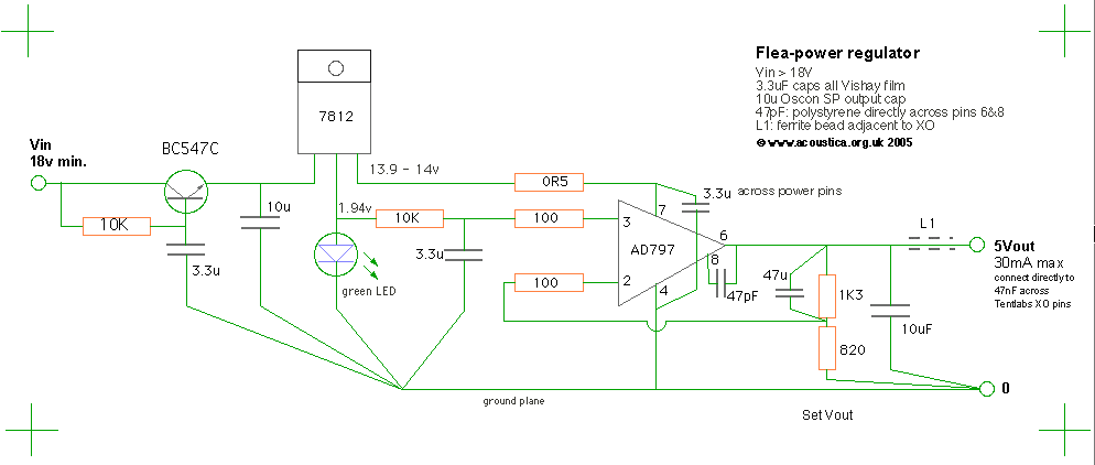
Next comes a conventional three-pin regulator to provide a stable, low impedance
supply to the circuit. The 7812 doesn't actually have to be very good at all - we don't
even much care about its behaviour as a regulator here, since the AD797 has up to
130dB(!) of power supply noise rejection at low frequencies. The reference leg of the
7812 is basically the output of an internal current source, which we take advantage of
to drive our voltage reference - a regular green LED - which gives about 1.95v. This
reference output is followed by another 10k/3.3uF filter. All 3.3uF caps are film types
to avoid adding leakage noise.
So to implement that into the superreg we have this:
Im going to try it out as its easy enough to add it, although space is a tight.