advertisement


DIY Geddon - LP12 power supply

RichardH

Bodging pleb
Right, for those wondering, the Armageddon is an off board power supply made by Naim Audio for the Linn LP12 turntable.
It is possible to make your own very similar power supply with some simple components.
Have a look over at Neil McBride's website for more background to this - there's a lot also on The Vinyl Asylum - do a search for "DIY armageddon".
One this to stress before we go any further is that this is all at your own risk, mains voltages are involved, your Linn/Naim dealer may never talk to you again, etc etc.

....Oh, and finally, I've tried to make this as understandable as possible, but IF YOU DON'T understand it, then I suggest you spend a bit more time reading up on the basics before attempting this - electricity can kill!
 
Thought it might be useful to see some pics of what you're going to be dealing with, so here goes.

First things first - unplug your LP12 a good while before you get started, as the capacitors on the Valhalla board will take some time to dischage, and could give you a nasty shock.

Make sure you remove the platter and lid before you move the Linn - I was also able to take the arm off, as it's a Naim Aro, and easy to remove. If not, put the stylus guard on, and make sure the arem won't move around and get damaged.

First thing you'll need to do is get the baseboard off. This is held on with 6 screws - one in each corner which also hold the feet in place, plus two in the centre of front and back. Make sure the Linn is well supported while you remove these!!

Once the baseboard is removed, you can see what you're dealing with. The big circuit board in the pictures below is the Valhalla, which will be superceded by the Geddon. These can go for decent money, so it is work taking care when removing it - be careful not to flex the board too much wehn dismounting it, as this may crack the PCB tracks.

LP12 from the rear

LP12_overview_rear.jpg

Here's the Linn with platter, arm (Naim Aro - nice and easy!) and lid removed, viewed from the rear.
It's sat between two Ikea Lack tables, so there's plenty of access to the underside.


Underneath the LP12 with the baseboard off

LP12_underneath.jpg

OK, the baseboard´s off, and here you can see the guts of the Linn. The Valhalla power supply is the green circuit board. This the what's going to be removed, and replaced by the off board Geddon.
Note the armleads and power cables coming out from the back (top of picture), and the motor (gold coloured, top right).


Close up of the LP12 motor

LP12_motor_valhalla.jpg

Here's the motor close up, showing the four wires leading to the Valhalla board.
 
Last edited:
Here's the basic circuit, plus a twiddly one I'm trying out, based on suggestions from over on the Vinyl Asylum.

Component values seem to be the following:
R1 - 3.3K
C1/C2 - in fact, you can use 1 capacitor of 0.22uF (220nF), but a closer match is by summing two 0.1uF caps to make 0.2uF. I've used 250V polyester caps.


Basic Armageddon Circuit

armageddon.gif

Here's the basic circuit. I can confirm that the red wire goes to the top connection - i.e. the one without the capacitors.


Tweaky Armageddon Circuit

armageddon_2.gif


The red letters refer to the photos of my circuit below.
This is basically the same as the other circuit, but with a switch to drop the resistance for initial start up of the turntable, and a variable resistor to allow me to increase the resistance to drop the voltage down as much as possible to minimise motor vibration. X and Y are the where the red and blue wires attach - Z is the connection for the two grey wires.

Having lived with this for a while now, I'd say don't bother with the load switch or variable resistor - it's just as easy to start the TT with a bit of help spinning the platter. You may want to experiment with different resistor values though. I ended up with around 6k8.
 
Last edited:
Right, so you've stripped the Linn, you understand the circuit, you need the components. The main component is going to be the transformer. It will be the majority of the cost, and is the thing that can kill you, so MAKE SURE YOU UNDERSTAND WHAT YOU'RE DOING!

It took me a while to get my head round these beasts, and I'm no expert, but for what it's worth, here's some info.

The transformer does what it says - it transforms mains voltage to a different one. That's it. We want a final voltage of around the 110v level, so we need a transformer that converts the supply voltage (240v) to 110v.

There are loads of different types, but the type we are using for this is a toroidal transformer - it looks like a doughnut.

If you look for a toriodal transformer, they will come in a variety of flavours - centre tapped, dual secondaries, etc. Have a look below for a photo of a couple, and notice the scary number of wires coming out of them - particularly the one on the left.

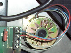
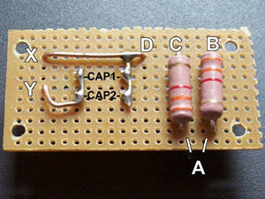
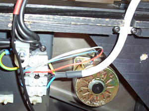
Look at the circuit diagram above - the bit labelled T1 is the transformer. If you look on the transformer itself, you'll see a similar picture, (see closeup), with the wire colours labelled.

Now as we're in the UK, we need the primaries (the left hand side of the diagram - where the supply comes in) to be set to 240V. Looking at the close up picture, you'll see that we have two sideways "U" with 0 at one side and 120v at the other. This is a dual primary setup. To make it work for 240 volts, we need to join the centre 120v (labelled grey below), and the centre 0v (labelled vio below). This then gives you the setup as shown in the circuit above.

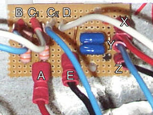
The secondaries are more interesting, as there will be a variery of options. You may be lucky and just get a single set of leads out, like the one shown below - black and red. More likely there will be dual secondaries. In this case you may have two 55v secondaries, so join them in a similar way to the primaries - middle wires together. I found this page quite handy for seeing the different configurations a transformer can be used in - remember that the wire colours will vary by manufacturer.

Mounting the transformer
The transformer should come with a mounting kit - this will comprise a bolt, nut and washer, plus a large steel "washer" and rubber gasket (I know it's not really a gasket, but that's the best description I can give). Both are about two thirds the size of the transformer.

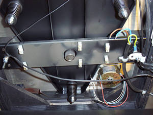
Decide where the transfomer will go in your case, then mark a centre point. Drill a hole large enough to pass the bolt through. Then sit the transformer on the rubber "gasket", and sit the large steel plate/washer on top, with the "bump" downwards. Pass the bolt up from underneath, through the hole in the top plate, and fit washer and nut. Tighten, but not TOO hard.
Make sure that the bolt cannot touch the top of the case, as this might allow current to pass through the centre of the toroid - a very bad thing.

Wiring it up
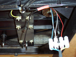
When joining the wire, make sure the connection is good - I soldered, then put insulation tape tound and finished off with a bit of shrinkwrap to keep things tidy. I have used crimp (spade) connectors on the ends that are going to the supply and board - the switch is bound to have these, and it makes things much easier to connect.

To use a spade connector, insert the wire into the top (narrow) end, and crimp it hard to hold the wire in place (best if you have the proper tool - you can buy sets with connectors and tool from most cheapy market tool stalls for about £2). I've also discovered some nice ones that you can solder the wire to, and use some long nose pliers to crimp on to the insulating later. See parts list below for more details. So, finally, in my case I'll be connecting the incoming mains voltage to my blue and brown wires, and the circuit board will be connected to the red and black wires.

Toroidal Tranformers

toroidals.jpg

A couple of toroidal transformers, a 300VA on the left, and a 530VA on the right. Big and heavy!

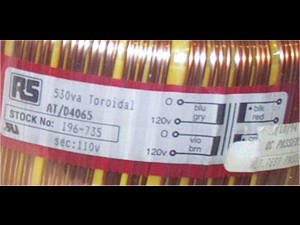
Close up of Toroidal label

toroidal_close.jpg

Here's an example label for a toroidal. This one's fairly simple - note the sticker covering the bottom half, as it's only got a single secondary.
 
Last edited:
Here's my circuit, banged together. I didn't use stripboard, as I thought thicker connections would be better, so it's all hardwired using solid core wire (I just stripped a bit of twin and earth mains cable - the stuff you use to wire a house). If you don't have any of this (and you have to buy it on 50m rolls), then you can probably get away with bending the excess wire on the resistors and capacitors to fit. The letters refer to the circuit diagram above.

A is the connection for the transformer
My switch will go between B and C to drop the resistance (and therefore increase the voltage to the motor) for start up.
A variable resistor will go between C and D to allow me drop the voltage as much as possible (hopefully this will be a one off twiddle, but comments on the Vinyl Asylum suggest that it may drift and so need occasional adjustment).
X and Y will be the connections to the red and blue wires from the LP12 motor.

For any internal wiring, I'd just strip some mains cable into its individual cores - if you have bought some 4 way cable to run the power from the Geddon box to the LP12, then get a bit extra, and use some of that.

Note that - especially if you skip the variable resistor and switch etc, it's perfectly feasible to mount the circuit board under the LP12, so you would then only need to run a 3 core cable from the transformer secondaries to the board.

My Armageddon Circuit - top

geddonboard_top.jpg

View from above. Black lines are just my marker pen scribblings. Resistors are underneath to keep it simpler - see other images for the underside.

My Armageddon Circuit - underside

geddonboard_under.jpg

The underside of the board.

My Armageddon Circuit - underside flipped

geddonboard_under_flipped.jpg

The underside of the board again, with the image flipped so the components have the same posiiton as on the image of the top.

The Geddon board all wired up
geddon_board.jpg

Here´s the board in situ.
Note this is slightly different from the other pics, but the principle is the same. I added "E" - connection for the other output from the transformer, which just goes straight through to the LP12 (connection "Z" as shown in the circuit above). Also I split the connection "C" into two, to make it easier to connect the wires. Also added spade connectors so I could get the board connected more easily.
 
Last edited:
The case for the Geddon is made up of 1.6mm and 10mm aluminium sheet. It's a half width case, and I've been a cheapskate and also squeezed in a power supply (tranny and rectifiers) for my 4 channel power amp (not at all flat earth).

It will generally be easier to buy a box "off the shelf". If you can, get an aluminium one - it's easier to cut and drill. By far the hardest part of handling the box is cutting the square/rectangular holes for the switch and IEC plug (yes, it's a panel mounted plug - the bit on the end of the mains lead is the socket!).

I tend to mark out the space required, and drill a hole in each corner. Then use a jigsaw with a metal cutting blade to join the corners, finishing off with a flat file. A Dremel is also great for hacking up aluminium, but hardly worth buying specially for this job - unless you want an excuse!

The blue and white cables running from the board to the left (front of the box) are for the resistance dropping "extra grunt" switch. The blue and white cables running to the right (back of the box) are to the 3W variable resistor.

I bought a 3 way socket and plug for the connection to the LP12, then realised that I needed a 4 way one. For the moment, I have retained this 3 way item, but put the earth as a flying connector separately. Next time I'm ordering, I'll replace this with the 4 way version. Or - mount the circuit under the LP12 and use a 3 way connector.


Inside the Armageddon

geddon_inside.jpg

Here's the completed Geddon box. It's actually got another transformer in there as well, supplying power to a 4 channel power amp for my surround channels. I've greyed out the non-Geddon parts - the smaller transformer and the 2 bridge rectifiers.

The cable connecting the Geddon to the LP12

geddon_cable.jpg

Here's the cable I used. It's 4 way cable, but currently only a 3 way connector, hence the flying earth. The 4 way junction block will be mounted underneath the LP12. I re-used one of the self tappers that held one of the original mains leads clips in place.
 
Last edited:
OK, we have the Geddon itself built, now to connect it up. LP12 back up on the tables, and a good light source underneath. Out comes the Valhalla board - there are 6 lugs it is mounted on - long nosed pliers and a bit of patience. It goes without saying that you have unplugged the turntable first! I released the motor, mains cable and switch ribbon cable before removing the Valhalla.

I removed the mains lead clips, and realised it would be handy to leave the earth cable connected, as I could use that to connect to my new earth lead, and not disturb anything else. So I cut that off and stripped it back ready to go into the junction box.

The second mains lead retaining clip attaches to the crossmember (you can see it in the first picture below) - I re-used one of the self tappers to fix my junction block in place - even re-using one of the holes the screws used before.

I found it easiest to connect the motor wires before mounting the connector block - be careful they are held down well, as they're fairly thin, and could miss the screw if you're not careful. <BR>

Valhalla board out

Geddon_LP12_under2.jpg

Here's the LP12 up on the ramps again, and the Valhalla board is out. Notice the 6 white lugs the board is mounted on - the middle pair is hard to get at - don´t force it!
Also note far left the ribbon cable that connected the Valhalla to the power switch.

Armageddon/LP12 wiring

geddon_wiring1.jpg

I've connected the motor wires to the junction block. Note the yellow/green earth wire I left from the original mains cable - I´ll use that to connect the new earth wire to the LP12.

Geddon connected

geddon_lp12_complete.jpg

Here it is ready for action. Note the hole drilled in the corner brace - ready to do the "bolt mod".
 
Last edited:
There have been some reports by others that their fuses blow on a regular basis. I must admit I've not had this problem. This seems to be solved by powering the primaries at all times, and using the front panel switch to power up the secondaries only. If you decide to go this route, you may choose to go for a switched IEC chassis plug, so you can at least switch off the primaries if you wish.

Remember that different configurations will be needed for those in 110V supplied countries - the transformer primaries may well be laid out differently, and another fuse value will be required.
 
Soldering Iron - 25W
Soldering Iron Stand with damp sponge
Long Nosed Pliers
Screwdriver (cross head)
Flat file
Wire cutters
Multimeter
Drill and drill bits
Good work area with decent light source
Hacksaw
Jigsaw with metal cutting blade (optional)
Dremel (optional)

Note - all parts numbers are from CPC.
Where I've not given a part number, I'm assuming you can get the item locally, or already have it in your bits box.

Solder
Heatshrink - CB00742 CB00741
Misc wire
Spade Connectors (push on terminals) - CN04716 (4.8mm) CN04718 (6.3mm) CN04720 (6.3mm right angle)
Covers - CN04723 (4.8mm), CN04724 (6.3mm), CN04728 (right angle hinged)
500VA (approx) Toroidal Transformer - Encapsulated: TF00812 Normal: TF00831
Flange Mount Fused IEC Plug - CN06437 (switched version CN06432)
2.5A Slow blow/Anti-surge fuse - FF00360
DPST Switch - SW01122 (NB this is a non illuminated switch, as there is some thought that the Neon in an illuminated switch may add noise to the circuit)
2 x 3K3 3W resistors - RE01852
2 x 0.1uF (i.e. 100nF) 250V polyester capacitors - CA01264
Bulgin 4 Pole Minature 3A mains plug and socket - CN04061, CN04062
4 way mains cable - Better to buy locally by the metre - CPC will only do it on 50m reels!
Terminal block - CN0707566
Case - EN81249 - Please note I have not tried this case, and you should make sure it is big enough for the parts - particularly the height of the transformer


advertisement


Back
Top