advertisement


Creek CAS 4040

Am I correct in assuming that rising ESR causes a given capacitor to gradually become more 'reluctant' to accept a charge? In effect, slowing the recharge time/recovery rate to full uF capacity?

I'm afraid the question doesn't make sense...

It's literally as it says, Equivalent Series Resistance. We want a capacitor to be a short circuit to AC and to deliver it's charge from a zero resistance source ideally. ESR spoils this by whatever the amount of ESR a cap has. It's highly frequency dependent and in the case of electrolytics, temperature dependent as well.
 
All finished.

20180112_093836[1] by Michael Pickwell, on Flickr

20180112_094801[1] by Michael Pickwell, on Flickr

Here's a summary:

  • All electrolytic capacitors replaced with the only deviation from factory spec being that I increased the capacitors on the output of the two regs from 1uF to 47uF (1uF just seems like a really measly amount of decoupling to me).
  • Local decoupling caps around the three op amps 'upgraded' from 100nF ceramic to more audiophile friendly 100nF polyester film.
  • Source selector switches, fuses, headphone socket and speaker connectors etc cleaned with DeOxit.
  • Volume pot, balance pot and tone controls relubricated with a drop of Faderlube.
  • Bias checked and readjusted.
  • Everything dismantled and cleaned.
The main voltage rails measured at +/- 30.7vdc so perhaps a touch closer to the 35v max rating of the smoothing caps than is completely ideal but since the last ones survived for 27 years I'm not going to lose sleep over it. I may swap them out for some higher voltage rated ones in the future.

I can provide a BOM if anyone wants it.

Ceramics are better for decoupling and there could be method to their madness in fitting only 1uF on the output of the regs. I wouldn't worry about it though.
 
Ceramics are better for decoupling and there could be method to their madness in fitting only 1uF on the output of the regs. I wouldn't worry about it though.

Hi Jez, thanks for stopping by.

Just to be clear, there's no other decoupling after the regs apart from the 100nF caps at the op amps. There are three op amps fed by the regs, a couple of TL072s and a single NE5532. I figured increasing the capacitance from 1uF wouldn't hurt and might actually have some benefit.

However it'll only take me 10 mins to whip out the 47uF's and pop some 1uF back in there (I have them in 'stock'). If you think it's safer to stick with the original spec?

Regarding the 100nF decoupling caps at the op amps, I have 100nF X7R in stock if you think they would sound better than the 100nF polyesters I've fitted?
 
Nice work Malcolm.

It looks like there are far fewer electolytics inside the 4240 than there are in the 4040.

I used:

2 x Cornell Dubilier 6,800uF 50V in the power supply
2 x Silmic 47uF 63V for the decoupling capacitors

The only other two I can see are close to the lower op-amp in the photo and they are decoupling the zener diodes used to get the +/-15v rails for the op-amps. They have no value on them and I've left them for now (the circuit diagram says they are 100nF).

There is, of course no phono stage built in so I'm looking for a Creek MM plug-in board. They're still available new but are pricey compared to the cost of a second hand 4240!
 
I doubt any of it would make much difference in practice... The 47uF's ideally should be poor quality ones, not low ESR etc. Ceramics, whilst crap in linearity etc unless COG type, have about the lowest ESR and inductance of all caps hence so often used for HF decoupling;)
 
I doubt any of it would make much difference in practice... The 47uF's ideally should be poor quality ones, not low ESR etc. Ceramics, whilst crap in linearity etc unless COG type, have about the lowest ESR and inductance of all caps hence so often used for HF decoupling;)

Indeed, for super fast opamps (e.g. OPA627 or AD797) I'd probably use a surface mount ceramic soldered to the pads on the underside of the PCB.
 
I'm afraid the question doesn't make sense...

It's literally as it says, Equivalent Series Resistance. We want a capacitor to be a short circuit to AC and to deliver it's charge from a zero resistance source ideally. ESR spoils this by whatever the amount of ESR a cap has. It's highly frequency dependent and in the case of electrolytics, temperature dependent as well.

Cheers Jez, obviously my ignorance is showing but I do appreciate your taking the time to respond.

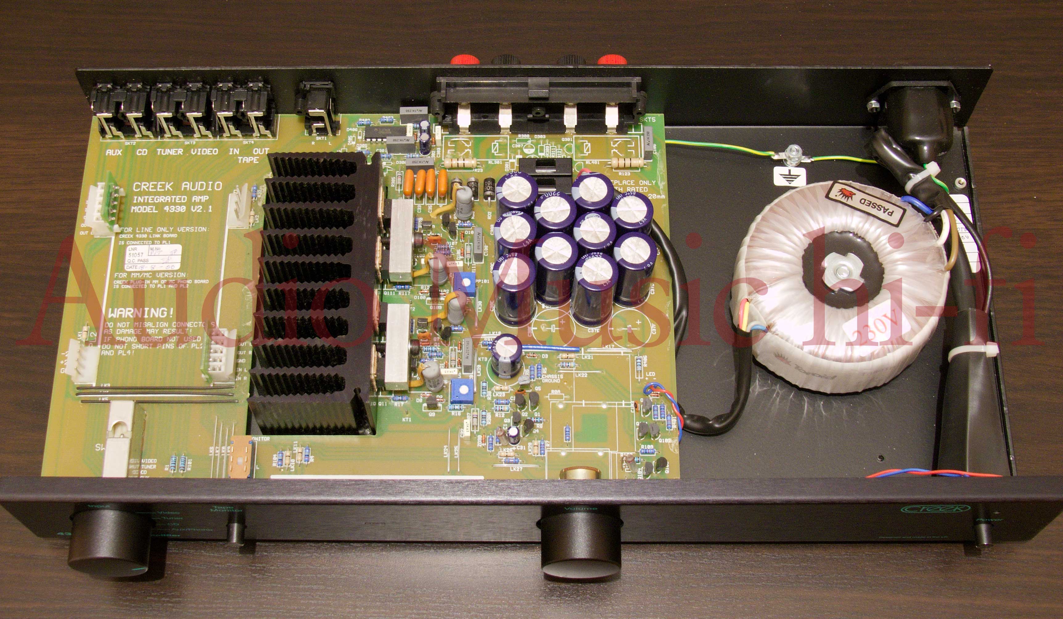
While on the subject of power supply smoothing capacitors, what are the advantages or otherwise of having clusters of smaller one's, as in 4330? Is it simply a matter of getting a higher total capacitance to fit within the low profile chassis?

4330mkII-open-f-La.jpg
 
Last edited:
Here's the 4240 that I've just been working on. I replaced two reservoir and two decoupling capacitors, and the balance and volume controls which were noisy and didn't respond to treatment. I also cleaned all the switches and connectors.


I've never seen the inside of 4240 before. Seems a logical evolution of 4040/4140.
 
Cheers Jez, obviously my ignorance is showing but I do appreciate your taking the time to respond.

While on the subject of power supply smoothing capacitors, what are the advantages or otherwise of having clusters of smaller one's, as in 4330? Is it simply a matter of getting a higher total capacitance to fit within the low profile chassis?

4330mkII-open-f-La.jpg

Multiple parallel caps can give you lower ESR and inductance.
 
Thanks Mike.

BTW, I'm seriously impressed with your various projects pictured on your Flicker stream (hope you don't mind my scrolling on through form the Creek pics).
 
FWIW A high ESR in smoothing caps can mean more ripple *and* a higher dissipation inside the capacitor. That may warm it up, and increase the rate of further deterioration. However in some cases you may find a cap 'recovers' in modest use if it had been left unused for ages.

Similarly, I tend to wary of having too large a capacitor shunting the output of an active stabiliser chip. Some of them can burst into song if the see too much capacitance at RF. So I'd usually assume the builder knew best.

With many regulators it is not too much capacitance per se that's the problem but a specific range of capacitance, sometimes known as "the valley of death" due to its appearance on a graph, that's the problem. It is usually a good idea to use something much bigger than the min value on the right of this graph in order to swamp the effects of further local decoupling caps etc also going to ground from the regs output, ie if the reg is unstable for values between 220pF and 1uF then fit something like 22uF or more. This mainly applies to monolithic regs and will not be suitable in 100% of cases... The datasheet is your friend..

There are many topologies for regulators, especially when we consider discrete implementations, and therefore many possible output impedances, bandwidths, settling times, phase margins, compensation schemes and board layouts. It is therefore not really possible to give a "one size fits all" solution to the ideal value, dielectric, ESR or self inductance of a capacitor to suit all regulators. Some need a very low ESR, low inductance cap whereas others need appreciable ESR to lower the Q of a resonance with the synthesised output inductance of the regulator or even to change the position of an output pole.

When going for the ultimate in regulators with a discrete or semi discrete topology these "super regulators" are a real pain to get right and in ways which belie their seeming simplicity... a 25mm ground wire of 1mm wire may cause huge oscillation, with loss of regulation, but replacing it with a 10mm x 3mm wire cures it, it may be unstable with a 33uF cap of one make and fine with another make, adding a 0.1uF film cap across it may make it stable with either make of 33uF electrolytic or make it unstable with both, it may be stable on load but not off load or vice versa and this may take a change in the compensation cap value to cure... If building any sort of "super regulator" I urge all diy-ers to use only an approved PCB and to stick exactly to the recommended parts and wiring layout! Don't even attempt it on veroboard or tag board or change any component specs as it will very likely not work...
 
FWIW If I'm using additional rail caps on individual ICs or stages I add some small resistors in series with the rail fed to them. That reduces having the PSU see the 'caps at a distance'.

TBH though I dislike the IC regulators. For audio I'm more concerned with getting a smooth low-noise rail rather than one that is clamped to a predefined voltage.
 
It all depends whether one is going for minimum PSU source resistance of course... the cap and resistor per stage approach gives good isolation between stages but poor (high) source resistance.

It is not often in audio that we have any need for the extreme precision in voltage which can be provided by suitable voltage regulators but the very low internal resistance can be most useful in certain circuits..
 
Fortunately in my experience well designed amp stages can have a good rail rejection ratio, particularly at low frequencies. eg, ones that 'hang' everything off the rails via a constant current or current mirror or longtail pair.

I agree that the IC regulators can give a low source impedance. But a snag is that ones I tried in the past tended to output a lot of noise, particulary at HF. Which could then get into amp stages unless you added a passive arrangement anyway.

I ended up coming to the above conclusion when I found it gave lower noise and hum levels from amplifier systems. Both for audio and in quite fancy research applications like JET! However there will be situations where a precise predefined voltage will be needed.
 
Good PSRR is to be encouraged yes but not all topologies have this and in some cases redesigning for better PSRR would compromise other areas.
It's all horses for courses and balancing compromises against each other of course.


advertisement


Back
Top