teddy_pardo
Trade: Teddy Pardo
In the past two weeks Ive been spending time modifying my CDX. I have achieved great results so far and will post the modifications on a separate thread as soon as Im done. In the meantime I thought Id share some of the reverse engineering work that Ive done on the CDX.
The power supply
When used with an XPS, the CDX is powered by 4 power rails
+/- 22V for the six OP42 opamps
+/- 10V for the two DACs (one per channel)
Two +15V for the digital and mechanics
When powered by the internal PSU, the 22V and the 10V are both connected to a common +/- 20.5V rail, and the two 15V are connected to a common 13V rail.
The +/- 22V is internally regulated (317/337) to +/- 18V, then connected directly to the 6 OP42. Each OP42 gets a couple of 100nF SMT decoupling capacitors. These regulators are located at the back left of the PCB, near the DIN connector (these are the first candidates to be replaced by ALWSR, which is what I did)
The +/- 10V is internally regulated to +/- 5V to power the two DACs. For each DAC there are two 337 (one for the digital part and one for the analogue part). There is only one 317 for both the digital and the analogue (I dont understand why). In total 6 regulators located on the left side of the PCB. The negative analogue and the common positive will probably benefit from being replaced by ALWSRs.
The two 15V rails are first regulated to 9.3V and then to 5V. There is one 9.3V regulator per 15V rail, and then many 5V regulators are connected to the output of the 9.3V regulators. Note that the 9.3V regulators carry a current of about 1A (one of them has a heat-sink). They are located at the front of the PCB near the transformer.
The PDM100 (described below) gets two 317s, one for VDD1 and one for VDD2, as recommended by the datasheet. VDD2 is a candidate for ALWSR. These two regulators are located at the back of the PCB near the Burndys connector.
The circuit
Main components
PCM1702 DAC. Two are used, one per channel
TDA7073 Dual BTL power driver (for the servo). Two are used
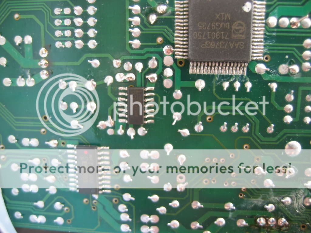
SAA7376 servo processor and CD decoder
74HC04D hex inverter
PMD100CQ HDCD decoder and filter. Datasheet can be found here
The crystal is connected to inverter #2. The output of inverter #2 goes to inverter #4, then to #5, then to #6. The output of inverter #4 (the first one) is connected via a 47R resistor to the PMD100, and the output of inverter #6 (the last one) is connected via a 330R resistor to the SAA7376 decoder.
Crystal -> #2 ->#4 -> #5 -> #6 ->
The PMD100 generates an internal clock which is used as an input clock for the two D/A converters (connected via two 10R resistors).
Note that the unlike other Naim CD players, the D/A converters are not connected to the inverter but to the BCKO (bit clock output, pin 34) of the PMD100. The diagram is shown on page 19 of the PMD100 datasheet.
One strange thing though is that the PMD100 datasheet says: The PMD-100s internally generated jitter on the bit clock output is lower when it is operated at 256 Fs when compared to 384 Fs (XTIM low versus high). When implementing the PMD-100 into a 384 Fs and bit clocked DAC design, we strongly recommend using re-clocking circuitry in order to attain the best possible sonic perfomance.
Although the CDX is running at 384 I have seen no re-clocking. So I guess that performance may be gained here (maybe it was done on the CDX2, anyone?).
I have not received yet my XO module so I cannot comment about the improvements of the Flea to the CDX, but given that the clock is not used to feed the D/A converters, I suspect that the Flea would not be as beneficial to the CDX as it is to other players. Martin, what do you think?
Im very interested in what has been done in the CDX2, anyone willing to share pictures?
The power supply
When used with an XPS, the CDX is powered by 4 power rails
+/- 22V for the six OP42 opamps
+/- 10V for the two DACs (one per channel)
Two +15V for the digital and mechanics
When powered by the internal PSU, the 22V and the 10V are both connected to a common +/- 20.5V rail, and the two 15V are connected to a common 13V rail.
The +/- 22V is internally regulated (317/337) to +/- 18V, then connected directly to the 6 OP42. Each OP42 gets a couple of 100nF SMT decoupling capacitors. These regulators are located at the back left of the PCB, near the DIN connector (these are the first candidates to be replaced by ALWSR, which is what I did)
The +/- 10V is internally regulated to +/- 5V to power the two DACs. For each DAC there are two 337 (one for the digital part and one for the analogue part). There is only one 317 for both the digital and the analogue (I dont understand why). In total 6 regulators located on the left side of the PCB. The negative analogue and the common positive will probably benefit from being replaced by ALWSRs.
The two 15V rails are first regulated to 9.3V and then to 5V. There is one 9.3V regulator per 15V rail, and then many 5V regulators are connected to the output of the 9.3V regulators. Note that the 9.3V regulators carry a current of about 1A (one of them has a heat-sink). They are located at the front of the PCB near the transformer.
The PDM100 (described below) gets two 317s, one for VDD1 and one for VDD2, as recommended by the datasheet. VDD2 is a candidate for ALWSR. These two regulators are located at the back of the PCB near the Burndys connector.
The circuit
Main components
PCM1702 DAC. Two are used, one per channel
TDA7073 Dual BTL power driver (for the servo). Two are used
SAA7376 servo processor and CD decoder
74HC04D hex inverter
PMD100CQ HDCD decoder and filter. Datasheet can be found here
The crystal is connected to inverter #2. The output of inverter #2 goes to inverter #4, then to #5, then to #6. The output of inverter #4 (the first one) is connected via a 47R resistor to the PMD100, and the output of inverter #6 (the last one) is connected via a 330R resistor to the SAA7376 decoder.
Crystal -> #2 ->#4 -> #5 -> #6 ->
The PMD100 generates an internal clock which is used as an input clock for the two D/A converters (connected via two 10R resistors).
Note that the unlike other Naim CD players, the D/A converters are not connected to the inverter but to the BCKO (bit clock output, pin 34) of the PMD100. The diagram is shown on page 19 of the PMD100 datasheet.
One strange thing though is that the PMD100 datasheet says: The PMD-100s internally generated jitter on the bit clock output is lower when it is operated at 256 Fs when compared to 384 Fs (XTIM low versus high). When implementing the PMD-100 into a 384 Fs and bit clocked DAC design, we strongly recommend using re-clocking circuitry in order to attain the best possible sonic perfomance.
Although the CDX is running at 384 I have seen no re-clocking. So I guess that performance may be gained here (maybe it was done on the CDX2, anyone?).
I have not received yet my XO module so I cannot comment about the improvements of the Flea to the CDX, but given that the clock is not used to feed the D/A converters, I suspect that the Flea would not be as beneficial to the CDX as it is to other players. Martin, what do you think?
Im very interested in what has been done in the CDX2, anyone willing to share pictures?
")