Hi all,
Here's a rough guide to HackerNAP building. It's incomplete, inaccurate, and omits stuff. Enjoy!
Latest BOM (v1.8): http://hackernap.com/docs/HackerNAP BOM v1.8.xls
Latest build manual (v1.4): http://hackernap.com/docs/Build Manual v1.4.pdf
HackerNAP Gerber files: https://www.dropbox.com/s/dw2rh9ik1tlsln6/HackerNAP Gerber Files.zip?dl=0
HackerCAP Gerber files: https://www.dropbox.com/s/256qweqeluxon81/HackerCAP Gerber Files.zip?dl=0
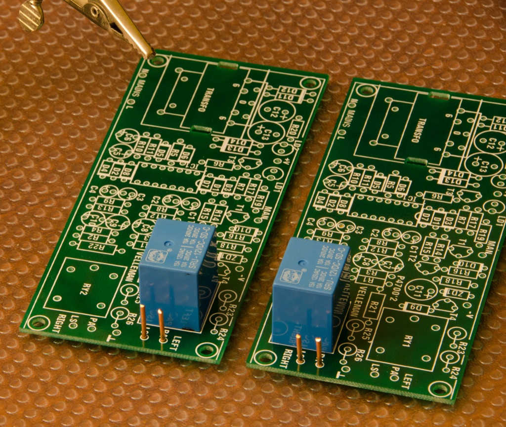
I started with boards that were mostly built except for the input cap, driver transistors, output caps, output inductor, and output transistors, and 5mm spade connectors.s the wrong way round!! Don't do that at home...
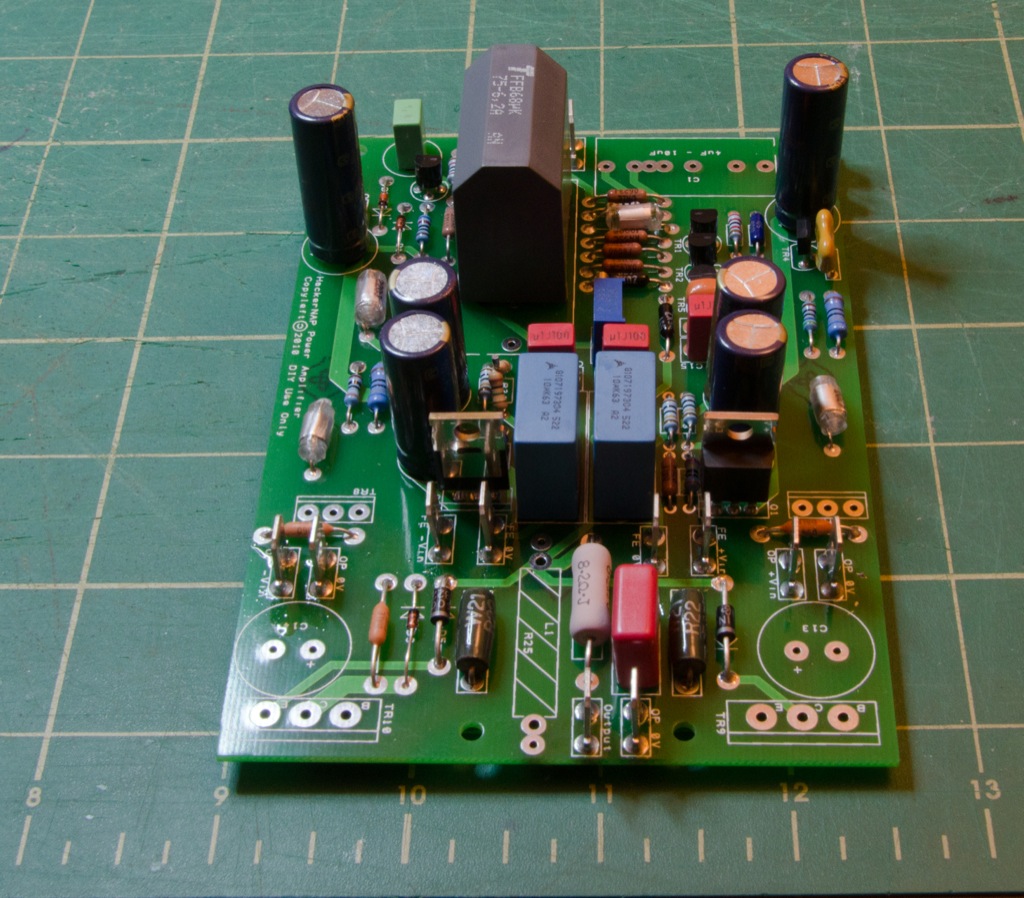
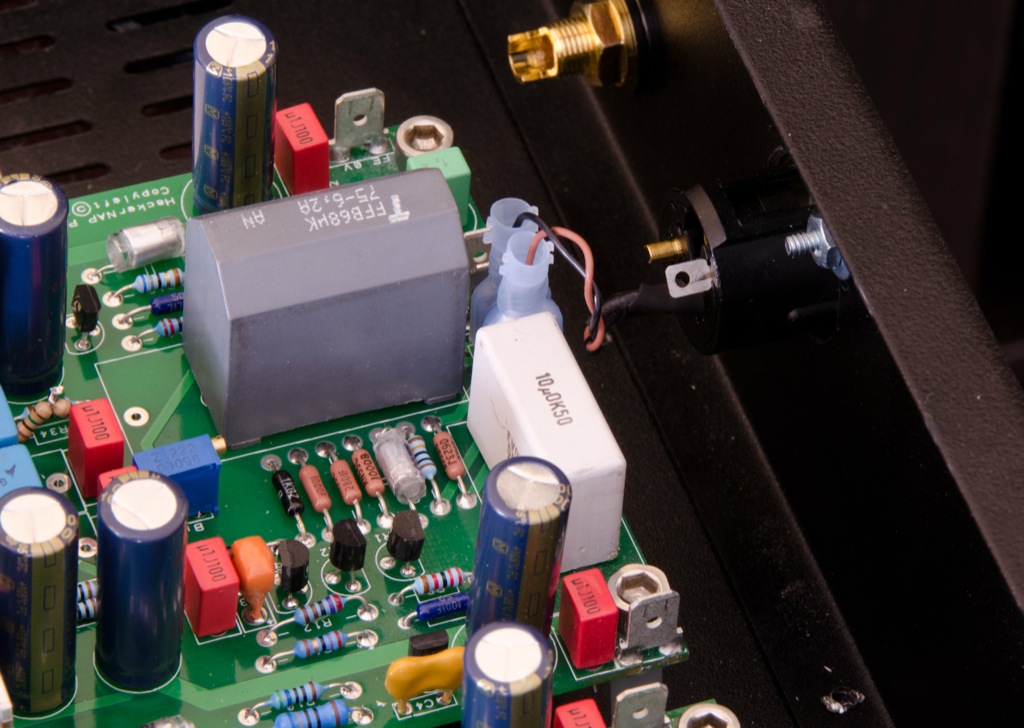
The big grey feedback cap is a 68uF AVX:
Here's the raw parts for the output inductor. I used 16 inches of 16AWG solid core enameled copper per inductor. Each was wound around a 1/4" drill bit and the ends are scraped free of enamel using my pocket knife:

Pop the resistors inside the inductors, like so:

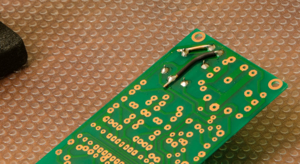
Then solder them into the hackernap and make sure that in a continuity test they measure 0 Ohms - no resistance whatsoever. If you measure anything else, go back and check your soldering:
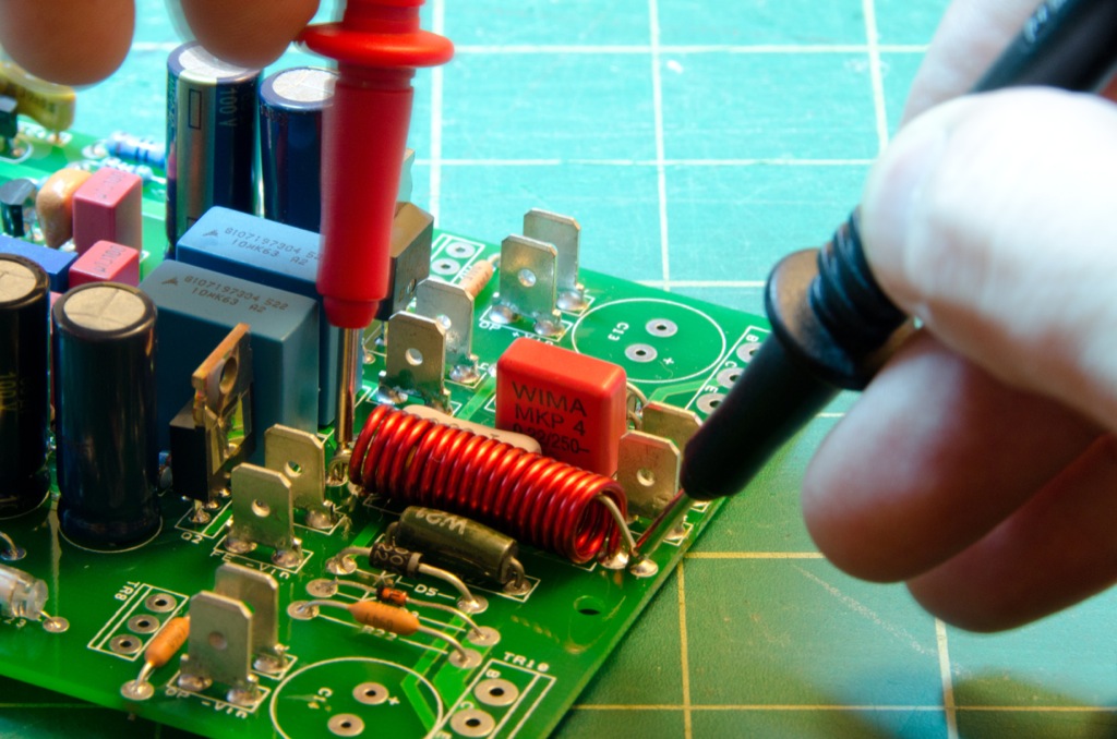
Voila! Inductor:
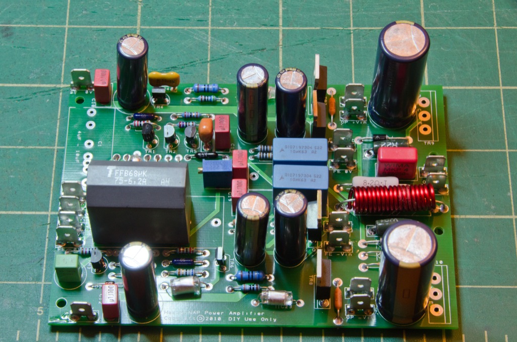
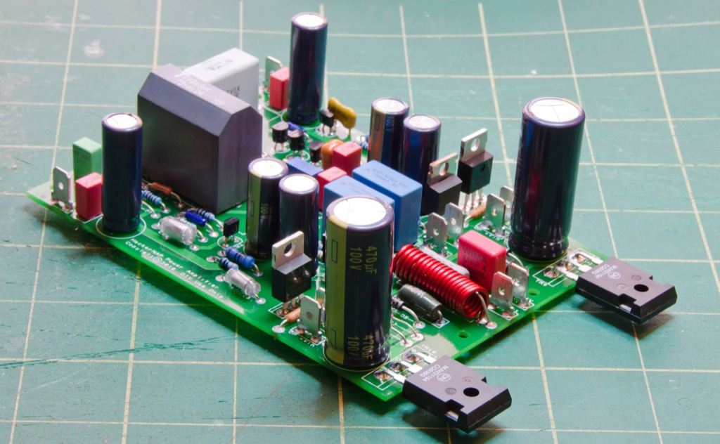
Add in the input coupling cap (a lovely 10uF Evox SMR in this case), the driver trannies, the output trannies, and the output caps:
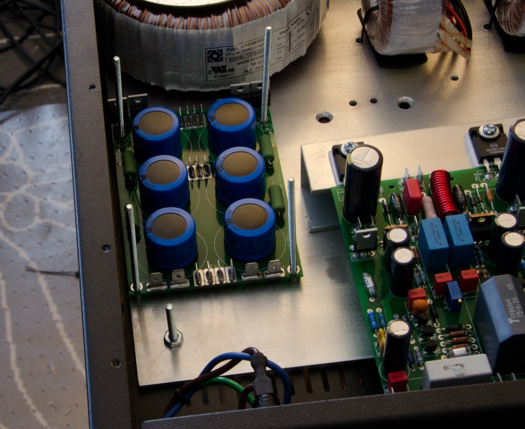
Build up your front end HackerCAPs (this is 1000uF/4R7 with Qspeed 3A diodes):
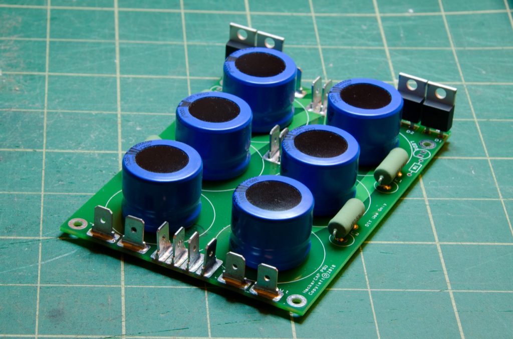
And your output stage HackerCAPs (6800uF Kendeils with Dale 10mH/8A inductors and 30A Qspeeds). Take note! Fit the 5mm spade connectors first or you're going to have a bollocks of a job fitting them after the caps:

The output trannies will be mounted on this chunk of aluminium, which has been drilled to accommodate the transistors:
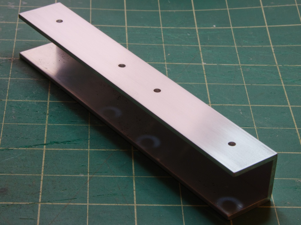
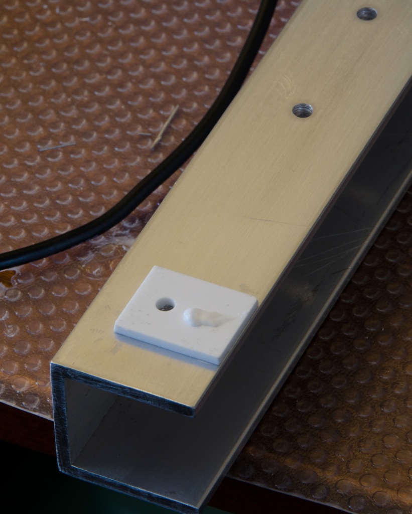
The bottom of the heatsink has been drilled and tapped with 1/4" threads so that I can bolt up into it from the underside of the amp, pulling it tight against the floor of the amp. This picture doesn't show it well, but those are 1/4" taps:

The heatsink bracket will be bolted to a 1/4" thick piece of aluminium that's bolted to the floor of the amp:
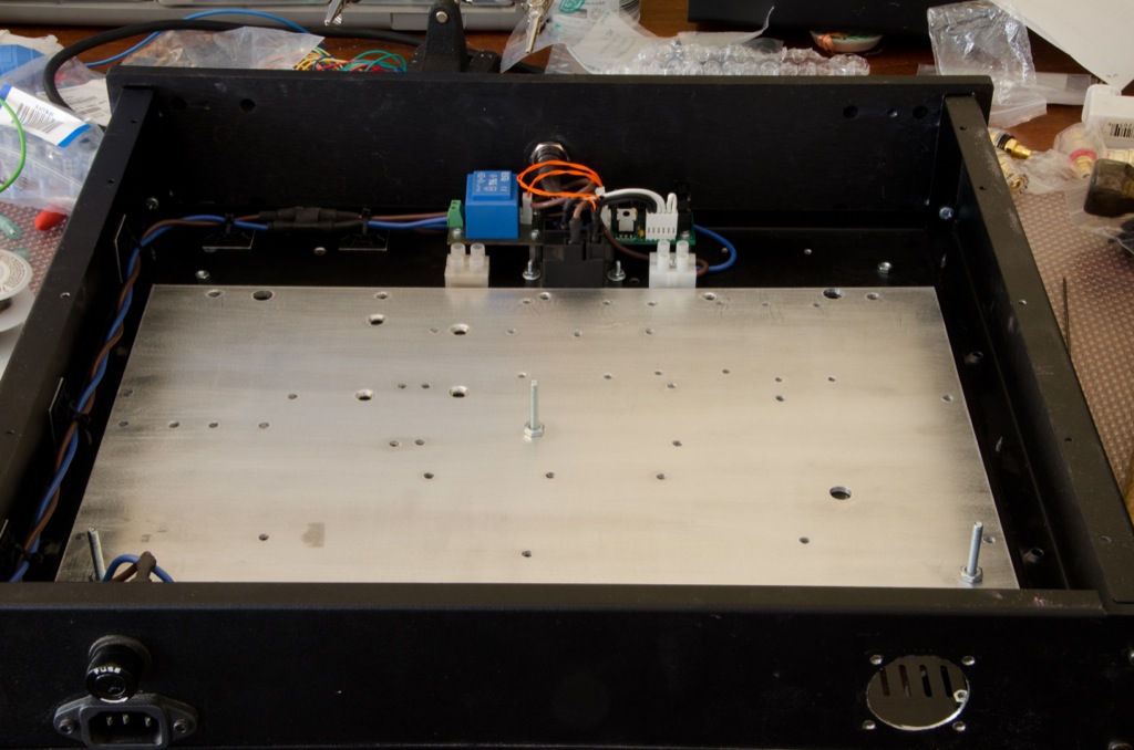
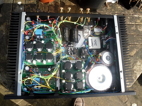
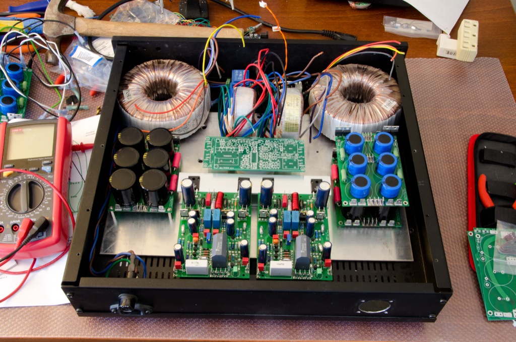
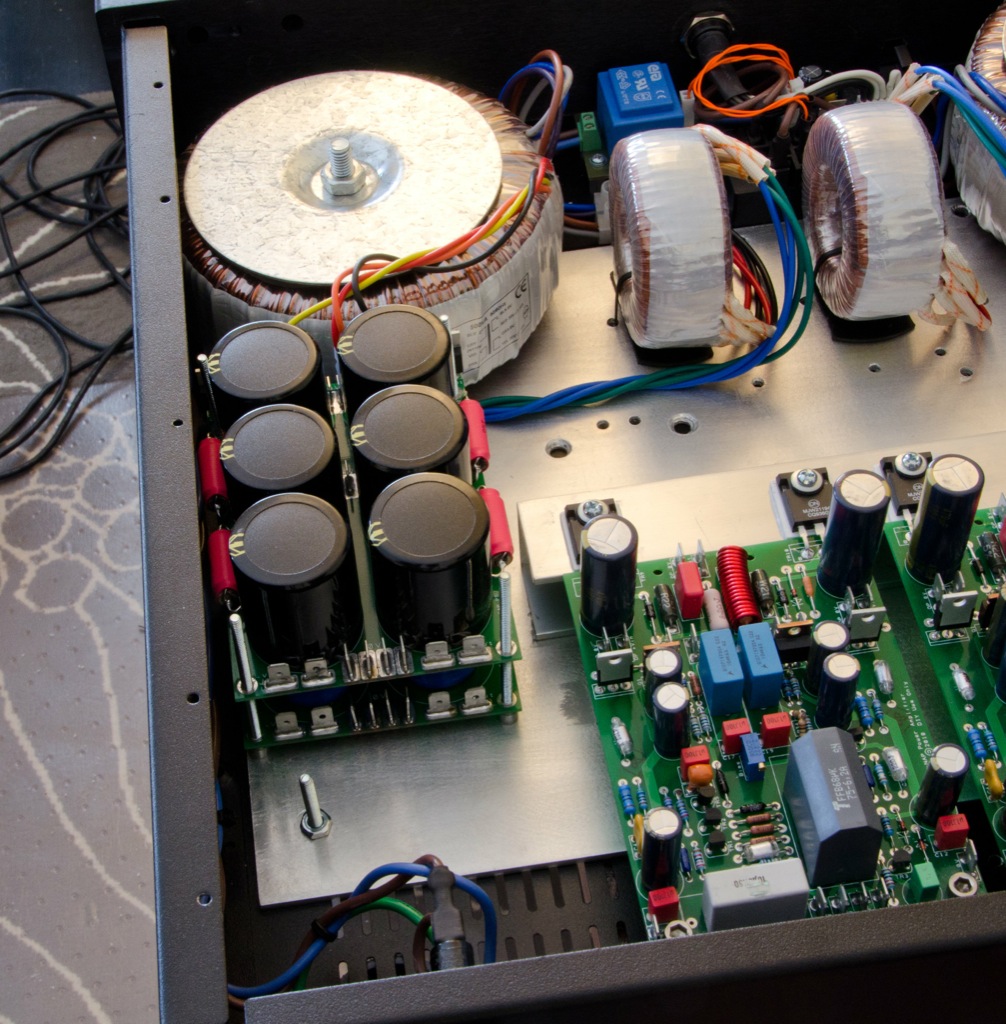
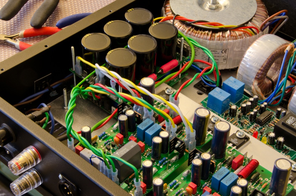
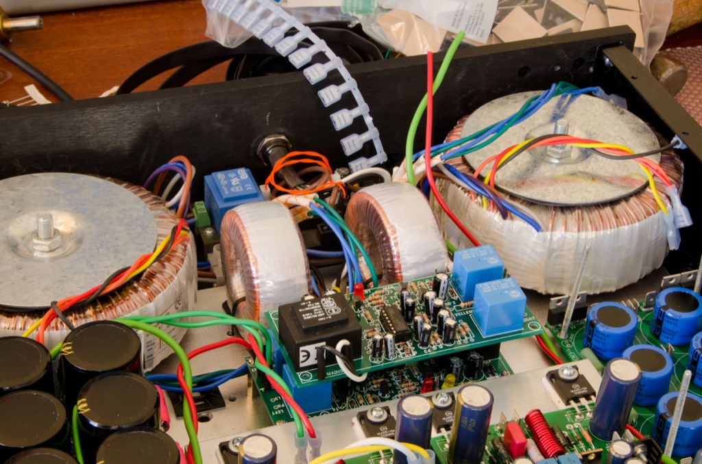
The plan was to lay it all out like this. It's 4 trafos, 2 Vellemans, 4 HackerCAPs and 2 HackerNAPs squeezed into a Modushop 2U Pesante case, which had previously been doing duty as a power supply (hence the big-ass hole in the rear panel):
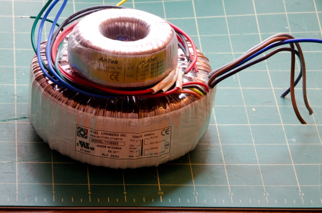
These are the transformers. Two 40-0-40 50VA for the front ends, and two 35-0-35 500VA for the output stages:
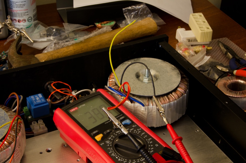
Test your AC before attaching it to stuff you care about!!
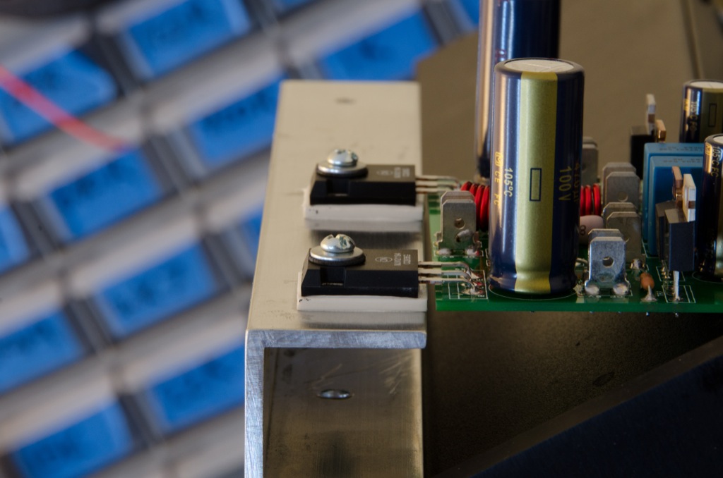
I'm using thick aluminium oxide heatsink pads. The underside gets a nice tiny blob of heatsink paste like this, which is then smeared evenly across the pad. It's then up-ended and smooshed onto the aluminium heatsink. Another blob the same size is then applied and the output transistor is laid atop it, like so:
I'm using rubber insulated washers. Not because I want insulation, but because I think it's less likely to damage the transistors than a metal washer:
On the other end of the HackerNAP boards I'm using thin rubber hose to make stand-offs:

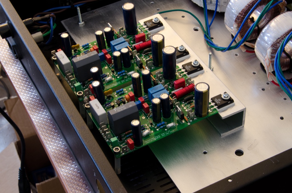
And here they are all mounted nice and snug:
The HackerCAPs are mounted on top each other, with the low-power caps on the bottom of the stack. The bolts are 2 1/2 inches long and I've used more of the rubber hose to make very small stand-offs for the bottom HackerNAPs:
The output stage HackerCAPs go on top:
When wiring the lower HackerCAP there's very little room for connectors. If you've got 90-degree push-on spades, that's great. I didn't have any, so I used regular spades, hacked off the top part of the plastic, added heatshrink, and bent the wire at 90 degrees like so:

All wired up, it looks like this:
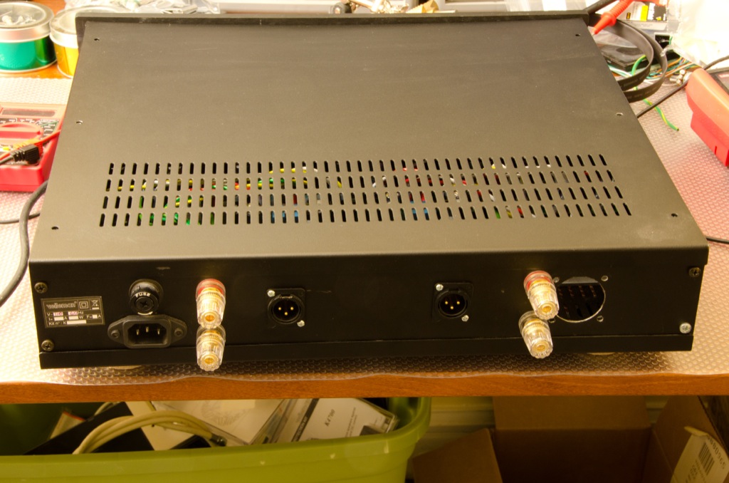
Input signal is via XLR connections:

And wired to the HackerNAP using really short twisted wires:
The speakers are protected by Velleman circuits. I was unimpressed by the standard pin connectors supplied with the Vellemans, so I bodged my own out of 16AWG solid copper:
First tests involve bias adjustment and running square waves through it to make sure there's no overshoot, undershoot, or distortion. Here's a 2.5kHz square wave being scoped at the HackerNAP's speaker output:

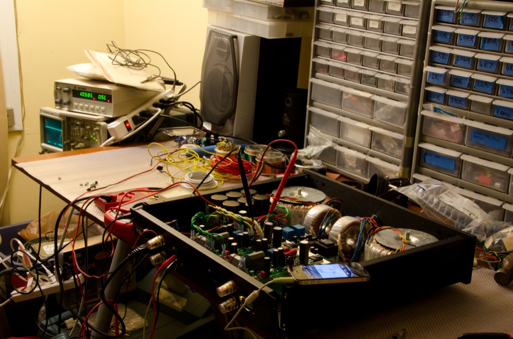
It looked good, so I hooked up my iPhone to play music through a shitty old speaker:
Finally the second channel was made in the same way:
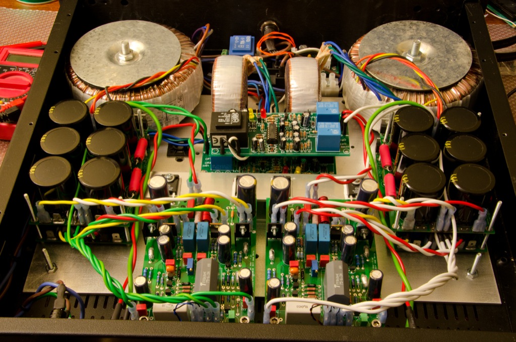
Notice that I've stacked the Vellemans on top of each other:
And with the lid on, it's ready for action in the main rig!
And there you have it - one HackerNAP. It sounds bloody brilliant")
Here's a rough guide to HackerNAP building. It's incomplete, inaccurate, and omits stuff. Enjoy!
Latest BOM (v1.8): http://hackernap.com/docs/HackerNAP BOM v1.8.xls
Latest build manual (v1.4): http://hackernap.com/docs/Build Manual v1.4.pdf
HackerNAP Gerber files: https://www.dropbox.com/s/dw2rh9ik1tlsln6/HackerNAP Gerber Files.zip?dl=0
HackerCAP Gerber files: https://www.dropbox.com/s/256qweqeluxon81/HackerCAP Gerber Files.zip?dl=0
I started with boards that were mostly built except for the input cap, driver transistors, output caps, output inductor, and output transistors, and 5mm spade connectors.s the wrong way round!! Don't do that at home...
The big grey feedback cap is a 68uF AVX:
Here's the raw parts for the output inductor. I used 16 inches of 16AWG solid core enameled copper per inductor. Each was wound around a 1/4" drill bit and the ends are scraped free of enamel using my pocket knife:
Pop the resistors inside the inductors, like so:
Then solder them into the hackernap and make sure that in a continuity test they measure 0 Ohms - no resistance whatsoever. If you measure anything else, go back and check your soldering:
Voila! Inductor:
Add in the input coupling cap (a lovely 10uF Evox SMR in this case), the driver trannies, the output trannies, and the output caps:
Build up your front end HackerCAPs (this is 1000uF/4R7 with Qspeed 3A diodes):
And your output stage HackerCAPs (6800uF Kendeils with Dale 10mH/8A inductors and 30A Qspeeds). Take note! Fit the 5mm spade connectors first or you're going to have a bollocks of a job fitting them after the caps:
The output trannies will be mounted on this chunk of aluminium, which has been drilled to accommodate the transistors:
The bottom of the heatsink has been drilled and tapped with 1/4" threads so that I can bolt up into it from the underside of the amp, pulling it tight against the floor of the amp. This picture doesn't show it well, but those are 1/4" taps:
The heatsink bracket will be bolted to a 1/4" thick piece of aluminium that's bolted to the floor of the amp:
The plan was to lay it all out like this. It's 4 trafos, 2 Vellemans, 4 HackerCAPs and 2 HackerNAPs squeezed into a Modushop 2U Pesante case, which had previously been doing duty as a power supply (hence the big-ass hole in the rear panel):
These are the transformers. Two 40-0-40 50VA for the front ends, and two 35-0-35 500VA for the output stages:
Test your AC before attaching it to stuff you care about!!
I'm using thick aluminium oxide heatsink pads. The underside gets a nice tiny blob of heatsink paste like this, which is then smeared evenly across the pad. It's then up-ended and smooshed onto the aluminium heatsink. Another blob the same size is then applied and the output transistor is laid atop it, like so:
I'm using rubber insulated washers. Not because I want insulation, but because I think it's less likely to damage the transistors than a metal washer:
On the other end of the HackerNAP boards I'm using thin rubber hose to make stand-offs:
And here they are all mounted nice and snug:
The HackerCAPs are mounted on top each other, with the low-power caps on the bottom of the stack. The bolts are 2 1/2 inches long and I've used more of the rubber hose to make very small stand-offs for the bottom HackerNAPs:
The output stage HackerCAPs go on top:
When wiring the lower HackerCAP there's very little room for connectors. If you've got 90-degree push-on spades, that's great. I didn't have any, so I used regular spades, hacked off the top part of the plastic, added heatshrink, and bent the wire at 90 degrees like so:
All wired up, it looks like this:
Input signal is via XLR connections:
And wired to the HackerNAP using really short twisted wires:
The speakers are protected by Velleman circuits. I was unimpressed by the standard pin connectors supplied with the Vellemans, so I bodged my own out of 16AWG solid copper:
First tests involve bias adjustment and running square waves through it to make sure there's no overshoot, undershoot, or distortion. Here's a 2.5kHz square wave being scoped at the HackerNAP's speaker output:
It looked good, so I hooked up my iPhone to play music through a shitty old speaker:
Finally the second channel was made in the same way:
Notice that I've stacked the Vellemans on top of each other:
And with the lid on, it's ready for action in the main rig!
And there you have it - one HackerNAP. It sounds bloody brilliant