
You are using an out of date browser. It may not display this or other websites correctly.
You should upgrade or use an alternative browser.
You should upgrade or use an alternative browser.
A valve line pre amp for the DIY fishy
- Thread starter Arkless Electronics
- Start date
martin clark
pinko bodger
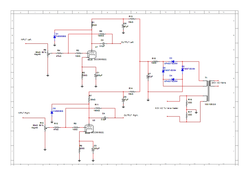
Cheap valve, and what, gain of 4x or so fixed by shunt feedback, plus simple cathode bias. Hard to go wrong ")
PS I like the call-out of UF4007 diodes - dirty cheap, and very effective/quiet in any low-current supply.
PS I like the call-out of UF4007 diodes - dirty cheap, and very effective/quiet in any low-current supply.
Arkless Electronics
Trade: Amp design and repairs.
What are the 150v zeners doing?
They prevent the voltage on the anodes from rising so high that 450V rated output caps need to be used and reduce the size of the turn on thump.
Arkless Electronics
Trade: Amp design and repairs.
It's just a generic 250V and 6.3V small mains transformer. This will be found to be the most easily available TX for valve use and various ones are available. You could of course wind the extra turns on to a toroidal isolating TX yes.
Barrymagrec
pfm Member
I`m quite tempted - it`s 44 years since I last built a bit of valve kit and I probably have all the bits somewhere - trouble is I don`t actually need it...
Arkless Electronics
Trade: Amp design and repairs.
I also designed an output mute circuit for it which grounds the output until the valve has warmed up but in the form above the circuit is so simple that the mute circuit doubles the complexity! I didn't want to put off the novice with having to also build a piece of SS circuitry on veroboard for the delay circuit, which a novice could find more challenging than the actual amp... It also of course requires rectifying and smoothing the heater supply in order to power the SS circuitry...
Arkless Electronics
Trade: Amp design and repairs.
Obviously experienced constructors will be able to go ahead with nothing more than the schematic, but if there is real interest I'll post a BOM for it with order codes etc and find a suitable TX people can order for it.
If wanting more than the one input then a source selector switch will be needed before the vol control.
I put the same design up on aos, with BOM, but no one built one and its all been deleted since so I thought I'd offer it up here and see what interest there was
If wanting more than the one input then a source selector switch will be needed before the vol control.
I put the same design up on aos, with BOM, but no one built one and its all been deleted since so I thought I'd offer it up here and see what interest there was
Arkless Electronics
Trade: Amp design and repairs.
I'll probably give it a go, thanks Jez - specs of a suitable TX would help
Cheers, Richard
0 - 250V @ >40mA and 0 - 6.3V @ >0.5A secondary, primary to suit your countries mains supply (still in 220V land these days Richard?). A centre tapped 6.3V winding is no problem and means you can get rid of R16 and 17 and connect the centre tap to ground.
Arkless Electronics
Trade: Amp design and repairs.
Between the bypassed cathode and the feedback loop, it should have decently low output impedance even without a follower.
IIRC about 120 Ohms ish. THD about 0.02%, FR about 5Hz - >100KHz. These are rough figures from memory of when I designed it and did measurements on the prototype.Barrymagrec
pfm Member
Very good of you to post it up Jez, hopefully it might encourage a few people to dip a toe into thermionic waters.
Arkless Electronics
Trade: Amp design and repairs.
Thanks Barry. It's ideal for a first build as it's as simple as it gets...
I found some old notes and it's about 450R output impedance, so still well low enough, THD 0.013% @ 5V RMS output so <0.01% at normal levels.
I found some old notes and it's about 450R output impedance, so still well low enough, THD 0.013% @ 5V RMS output so <0.01% at normal levels.
Last edited:
Dowser
Learning to bodge again..
0 - 250V @ >40mA and 0 - 6.3V @ >0.5A secondary, primary to suit your countries mains supply (still in 220V land these days Richard?). A centre tapped 6.3V winding is no problem and means you can get rid of R16 and 17 and connect the centre tap to ground.
Thanks - yes, in Swissieland still - think I may even have a spare TX, need to check.
Thanks, Richard
Simon Dawson
Angry, Ill & Ugly
Is it possible to reduce the overall gain to ~unity? I'm using a Leak ST 20 at the moment and the gain structure with most pre-amps is not ideal.
Arkless Electronics
Trade: Amp design and repairs.
Is it possible to reduce the overall gain to ~unity? I'm using a Leak ST 20 at the moment and the gain structure with most pre-amps is not ideal.
If you increase R4 and R10 to 180K that should do it.
Barrymagrec
pfm Member
If you increase R4 and R10 to 180K that should do it.
Won`t that only reduce the gain to about 2 or have I missed something?