Robert
Tapehead
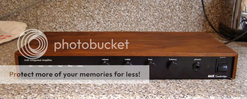
We could easily have never seen the A&R A60 amplifier.
Back in the 1970s John Dawson and Chris Evans got their heads together to build a small number of amplifiers for themselves and friends but word soon spread that their neat little A60 was a bit special, and the rest is history.
There are many reasons why so many A60s remain in use today, often in completely original form - not bad for what are in some cases thirty five year old amplifiers.
Chief among the reasons has to be the stability of the original design with no part of the circuit running close to component limits, allied to over-current speaker protection and fused outputs. But this is only half the story.
The other key design feature that set the A60 apart from the herd was sensibly implemented bandwidth limiting. Now, arguments will rage over the sonic consequences of such filtering but there can be no doubt that the little A60 succeeds because the designers sensibly limited it’s ultimate capability, both in terms of drive ability and bandwidth. The A60 gently rolls down outside the 20-20k band ensuring that the limited 35w of power is not wasted amplifying signals we cannot hear, or just producing waste heat.
While many A60 amplifiers are still performing well out in the field it must be said that many will be well below original specification by now. This is primarily due to the effect of electrolytic capacitors degrading over time, and the A60 contains many.
You will often see that the main PSU capacitors have begun to leak but all electrolytic capacitors have a limited shelf and useful life.
The very earliest A60 used discrete regulators for the pre amplifier and MM phono stages but these were soon replaced with LM317/LM337 chip regulators. Those early chip regulators are not as quiet or robust as modern versions.
Another area for consideration is the quiescent current setting for the output stage which may well have drifted over the years.
There are one or two excellent articles on the web detailing some quite radical modifications to the humble A60 but that is not the intention of this article.
What we seek is a cost effective and simple ‘service’ for this lovely old amplifier with the primary intention being to preserve the performance of the design,with perhaps one or two optional tweaks making use of better, modern components.
We now have access to small film capacitors and purpose specific electrolytic capacitors that were either not available back in the 70s or would have been prohibitably expensive for what was a £200 amplifier.
We will also cover repair and replacement of the output stage where this is necessary, so there is no excuse not to resurrect that old dead A60.
All part numbers are for RS Components.
First you need to remove the pcb form the chassis.
After removing to wooden sleeve, remove the control knobs and the four Lucas connectors from the mains switch, then remove the large nut securing the headphone socket to the panel. Flip the amp over and remove the three countersunk screws securing the front panel - then remove the front panel.
Now remove the four screws securing the output devices to the heat sink, gently levering the devices away from the sink (they’ll be stuck with sink compound). Unsolder the wires connecting to the speaker terminals and pull off the connectors linking the transformer and led to the pcb. You can now remove the pcb by removing the six screws holding it to the bottom plate. This is what you should have - fig 1 & 2.
Now cut the ties holding the two large PSU caps to the main board and unsolder them.
At the back of the pcb you will see four rail decoupling caps - C32/33/132/133.
Remove them and replace with Panasonic FC (part no 315-0940).
The FC is a low impedance capacitor and especially useful for rail decoupling and reservoir use though they can cause problems for regulators. This is what you should see - fig 3.
Large capacity reservoir capacitors can be expensive with 10000uf types often costing £12+ each. In this instance we are going to use the Vishay 056 PSM SI long life part at £6 each and bypass with a Panasonic 330uf FC. Because the Vishay parts are shorter than the original LCR capacitors we can use the original solder point on the pcb for the new Panasonic caps and connect the Vishay to the previously concealed points as shown here - fig 4.
Next, replace the four 0R22 2w carbon film emitter resistors - R64.
The original parts are carbon film and prone to drift and aging so we will replace them with a 2.5w wire-wound part (part no 485-1408) - fig 5.
Next replace the positive and negative chip regulators with modern LM317T/337T parts. The original regulators run hot and have a very thin metal base.
New parts should yield sonic benefits as the entire pre amplifier and phono stage draws current from these regulators. Be sure to orientate the regulators correctly (LM317 part no 533-8209 & LM337 part no 533-8221) - fig 6 & 7.
Now take a look at capacitors C9/109 just to the left of the volume control.
These couple the source signal from the volume pot wiper to the first stage of the pre amp. A cheap 1uf cap is fitted and so we will replace this with a good quality polyester film Wima part. Finding a suitable part for this location is hampered by the fact that most film caps are too large to fit but fortunately Wima produce a small 50v 1uf cap that fits perfectly (part no -118-038) - fig 8.
All of the capacitors used in the pre amp, tone control and driver sections are bog standard electrolytics. These perform many functions including coupling, response shaping and regulator decoupling. What we need are good quality multi purpose capacitors that don’t cost a fortune and will not upset the regulators by provoking peaking or oscillation. Elna Starget capacitors fit the bill nicely and being recently discontinued (non ROHS compliant) they can be bought cheaply while stocks last. See fig 9 & 10.
Replace capacitors C14/28/29/128/129/114/212/20/19/21/119/120/121/204 with Elna Starget 10uf 35v (part no -215-5685).
Replace capacitors C7/18/24/107/124/206/22/122/208/205/118/207 with Elna Starget 47uf 35v (part no -215-5708).
Replace capacitors C2/102 with Elna Starget 4.7uf 50v (part no -215-5736).
The next section deals with the signal path to the speakers and the output protection fuses.
I am not recommending that you bypass the fuses - that must be your decision and you should be aware that should a fault condition occur you may damage the amplifier and speakers. However, with the A60 we have two sets of speaker outputs - switched and ‘direct’.
The switched sockets connect to the output stage via both the headphone socket and it’s associated thin ribbon cable, plus the in-line speaker fuses. The direct outputs bypass the headphone socket but the fuses remain in the signal path. If you wish to make the ‘direct’ outputs truly direct, connect a piece of short cable from the Red terminals to the output filter inductor as shown below. You can snip away the red wire connected to point ‘D’ on the pcb.
Take care to observe left/right channel orientation when you come to solder the cables to the sockets. See fig 11.
Lastly, clean all switches and potentiometers with switch cleaner before re-assembling the amplifier. Be sure to use heat-sink compound on the output transistors and fix them firmly to the sink. You may wish to use a heat sink pad as shown below which avoids the rather messy silicone based compound - see fig 12.
When the amplifier is re-assembled, rotate the pcb mounted bias pots shown below fully anti-clockwise and switch on the amplifier. If all looks well, check for DC across the output sockets - it should be <30mv.
After a few minutes measure the voltage across the emitter resistors R63 for both channels and slowly rotate the trim pots until you reach 6mv. See fig 13.
Now replace the wooden cover and summon the maid to bring you some tea while the amp warms up. Leave at least 30 minutes before proceeding further. See fig 14
")
After about thirty minutes, adjust the trim pots to achieve 8-9mv across R63 on each channel which will give you 40-45ma quiescent current through the output stage. Check again for any drift after another 30 minutes. DO NOT EXCEED 10mv/50ma - the amplifier will run too hot in use.
Check the DC off-set again and if all is well you can complete re-assembly.
Arcam recommend placing a 15 ohm resistor in place of the positive DC line fuse and measuring voltage drop to set bias. You can use this method but please be aware that you are now measuring the current draw for the entire amplifier circuit and not just the output stage. Use the the emitter method mentioned above - it is more accurate.
So there we are.
You should have a fully operational A60 that sounds like new - if not a little better. If you don’t intend to use the phono stage you can usefully remove the socketed 5534 Op amps and relieve some stress on the regulators.
Total cost of parts should be around £30.
Part two of this article will show how to repair a blown output stage and Part three will focus on reviving the partnering T21 Tuner - another little gem that has been largely forgotten.
Illustrations and pics:
Fig 1.
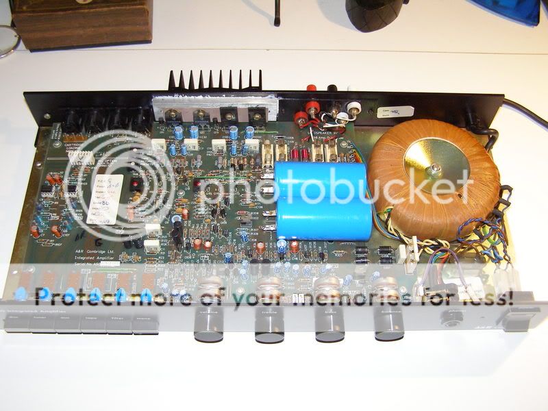
Fig 2.
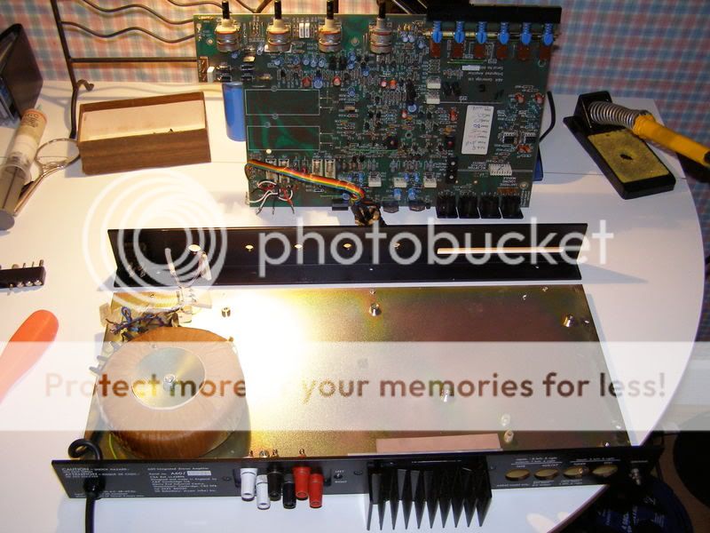
Fig 3.
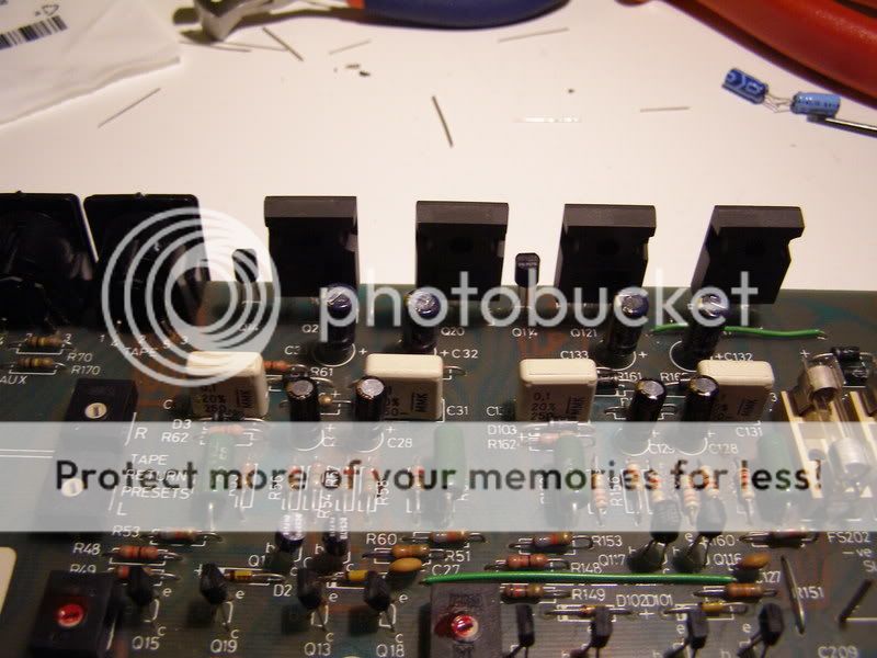
Fig 4.

Fig 5.
Fig 6.
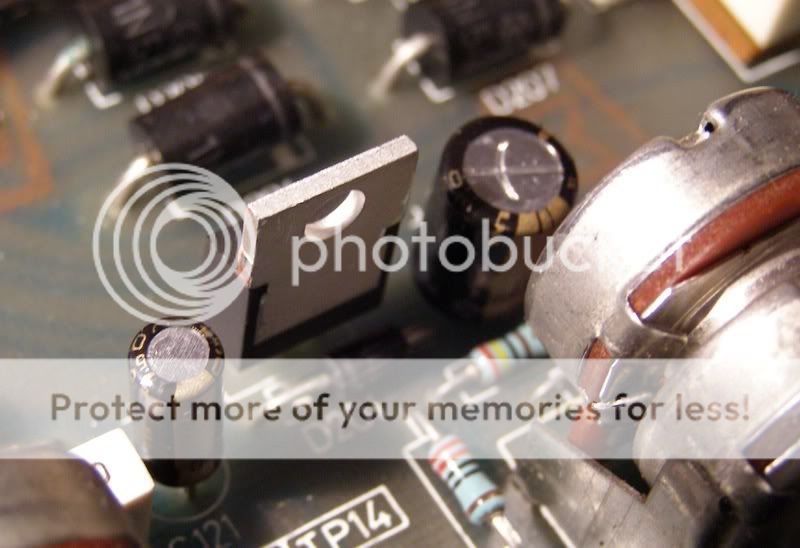
Fig 7.
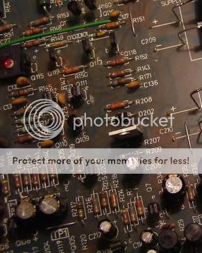
Fig 8.
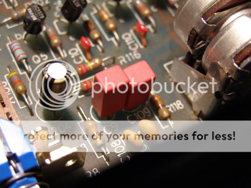
Fig 9.
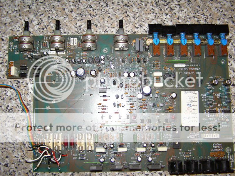
Fig 10.
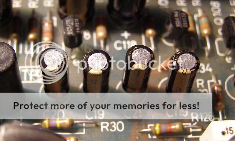
Fig 11.
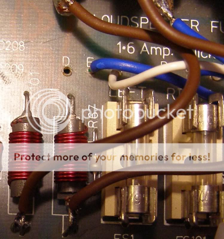
Fig 12.
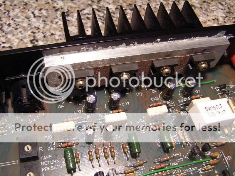
Fig 13.
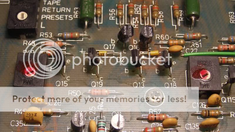
Fig 14.