
So with these three pin fellas, I guess that two pins are to be used in series with the circuit like a normal resistor, the other is a shunt to ground? And you've got it exactly, I'll pull the trimmers out of the circuits and measure them once I've found the ideal values.
You are using an out of date browser. It may not display this or other websites correctly.
You should upgrade or use an alternative browser.
You should upgrade or use an alternative browser.
Replacing the ALWSR's pre-regulator by a VBE
- Thread starter teddy_pardo
- Start date
Carl, like you, I have gone through almost all of the versions of this gyrator circuit, and arrive at the same conclusion: stick with the FET. ")
I have now directly compared BJT Darlington (547C/D44H11) and a FET (IRF 520) gyrator pre-reg in a number of circuits. Both versions were built with carefully constructed layout with minimum trace length between the filter components and approx. 5mm between last filter resistor/cap combo and relevant BJT/FET leg. Each time I have compared the two I have been impressed by how open, wide-band, uncolored, and precise the FET version performed. There is also a tremendous solidity and power to the presentation that is unlike the BJT Darlington versions. I do not know if the sound will get more free and mellower with time, but if you like rock music, the FET version is definitely for you.
I also designed one blind-fold A/B test to compare the BJT and FET control element within the same circuit (AD825-based ADC buffer) with two other audiophiles. They both preferred the FET version. The most striking feature of the FET-based version in this circuit was better LF extension, an aspect which is by no means trivial in a circuit packed with metal foil resistors and polyprop coupling caps. By comparison, the BJT pre-reg did less well at low frequencies, but had a deeper sound-stage for some reason, in part related to the sharper way it reproduced mid and higher frequencies. Everyone agreed that this was however an artificial effect, and that the FET version sounded "more linear" and "more rhythmically and tonally accurate."
It appears that the constant LF impedance of the FET version is relevant from a sonic and a from a power distribution quality point of view. By quality, I mean both the magnitude of the impedance, plus how well it is maintained over a large frequency range. Even if their very high voltage threholds severely limit attempts for low drop-out designs,the linearity of the FET output impedance and its dynamic performance make it very attractive as a control element in a gyrator pre-reg.
From this moment on, I am devoting my attention only to FET-based gyrators, even going through the hassle of replacing transformers in equipment where the transformer secondary voltage is too low to accomodate the higher drop-out voltage of the FET version. Catalogs are being consulted to source other varieties of FET to test against the IRF520, and plans are being made to implement TO-92-style FET gyrators in low-power regulation systems (including a flea or two ). It will be very interesting to see what sort of characteristics and performance the gyrator design results with different FETs. I hope to have some results to report in a month or two.
I have now directly compared BJT Darlington (547C/D44H11) and a FET (IRF 520) gyrator pre-reg in a number of circuits. Both versions were built with carefully constructed layout with minimum trace length between the filter components and approx. 5mm between last filter resistor/cap combo and relevant BJT/FET leg. Each time I have compared the two I have been impressed by how open, wide-band, uncolored, and precise the FET version performed. There is also a tremendous solidity and power to the presentation that is unlike the BJT Darlington versions. I do not know if the sound will get more free and mellower with time, but if you like rock music, the FET version is definitely for you.
I also designed one blind-fold A/B test to compare the BJT and FET control element within the same circuit (AD825-based ADC buffer) with two other audiophiles. They both preferred the FET version. The most striking feature of the FET-based version in this circuit was better LF extension, an aspect which is by no means trivial in a circuit packed with metal foil resistors and polyprop coupling caps. By comparison, the BJT pre-reg did less well at low frequencies, but had a deeper sound-stage for some reason, in part related to the sharper way it reproduced mid and higher frequencies. Everyone agreed that this was however an artificial effect, and that the FET version sounded "more linear" and "more rhythmically and tonally accurate."
It appears that the constant LF impedance of the FET version is relevant from a sonic and a from a power distribution quality point of view. By quality, I mean both the magnitude of the impedance, plus how well it is maintained over a large frequency range. Even if their very high voltage threholds severely limit attempts for low drop-out designs,the linearity of the FET output impedance and its dynamic performance make it very attractive as a control element in a gyrator pre-reg.
From this moment on, I am devoting my attention only to FET-based gyrators, even going through the hassle of replacing transformers in equipment where the transformer secondary voltage is too low to accomodate the higher drop-out voltage of the FET version. Catalogs are being consulted to source other varieties of FET to test against the IRF520, and plans are being made to implement TO-92-style FET gyrators in low-power regulation systems (including a flea or two
). It will be very interesting to see what sort of characteristics and performance the gyrator design results with different FETs. I hope to have some results to report in a month or two.PigletsDad
My intelligence test came back negative.
Hacker,
I have been thinking about how best to use the FETs.
Reducing the resistor value to get stability defeats one of the big advantages, and is a fairly ineffective method.
Instead I think you need to take two steps.
1) Use a stopper resistor to stabilise the FET (also suggested above by FDIECK).
This goes between the capacitor and the gate of the FET.
100 Ohms should be enough, although FDIECK suggests 250, but the IRF610 is reasonably low capacitance, so I think 100 should do the trick. Higher values give better stability, but will reduce rejection in the high RF. Lower values skirt with the risk of oscillation, but widen the rejection band upwards.
As FDIECK has said, mount the stopper absolutely right close up to the FET - this is a wideband RF circuit, even though it only produces DC!
2) Make sure the cap doesn't have a resonance at an embarassing frequency - this means not using too big a value close to the FET, say 0.1uF. Getting a lot of filtering probably means going to a two pole circuit.
So you want something like (warning ASCII art, may not come out)
Where G is the ground symbol, which I wasn't going to draw in ASCII, /\/\ is
a resistor, and so on.
The values shown are just nominal, but I vaguely remember you had some 4.7uF caps in stock.
In principle, the first resistor could be even bigger to give more low frequency filtering - 1M would give a 5s time constant, which would be well over 70dB down at 50Hz. But it would take nearly half a minute to settle! The values shown would give about 50dB rejection at 50Hz, and over 60dB at 100Hz (the main ripple frequency).
Alternatively, you could try just using the little CAP (0.1uF or whatever you have in your bits box), and 1Meg resistor. The stopper should keep it from oscillating, and you will get worthwhile filtering.
I have been thinking about how best to use the FETs.
Reducing the resistor value to get stability defeats one of the big advantages, and is a fairly ineffective method.
Instead I think you need to take two steps.
1) Use a stopper resistor to stabilise the FET (also suggested above by FDIECK).
This goes between the capacitor and the gate of the FET.
100 Ohms should be enough, although FDIECK suggests 250, but the IRF610 is reasonably low capacitance, so I think 100 should do the trick. Higher values give better stability, but will reduce rejection in the high RF. Lower values skirt with the risk of oscillation, but widen the rejection band upwards.
As FDIECK has said, mount the stopper absolutely right close up to the FET - this is a wideband RF circuit, even though it only produces DC!
2) Make sure the cap doesn't have a resonance at an embarassing frequency - this means not using too big a value close to the FET, say 0.1uF. Getting a lot of filtering probably means going to a two pole circuit.
So you want something like (warning ASCII art, may not come out)
HTML:
<pre>
Raw --/\/\---+---/\/\--+---/\/\-- Gate
     100K    |   100K  |     100
            _|_       _|_
Big (4.7uF) _ _      _ _  0.1uF
             |         |
             G         G
</pre>
Where G is the ground symbol, which I wasn't going to draw in ASCII, /\/\ is
a resistor, and so on.
The values shown are just nominal, but I vaguely remember you had some 4.7uF caps in stock.
In principle, the first resistor could be even bigger to give more low frequency filtering - 1M would give a 5s time constant, which would be well over 70dB down at 50Hz. But it would take nearly half a minute to settle! The values shown would give about 50dB rejection at 50Hz, and over 60dB at 100Hz (the main ripple frequency).
Alternatively, you could try just using the little CAP (0.1uF or whatever you have in your bits box), and 1Meg resistor. The stopper should keep it from oscillating, and you will get worthwhile filtering.
Slawney, I'm glad someone else is hearing what I'm hearing - and I agree completely, the performance across the whole audio band is just more natural... but the bass is where the benefits are really apparent.
PD, this is exactly the kind of information I was looking for - thanks a million for that. It looks like 2 pole is the way to go as I've got a bunch of 10u polys to use, so I reckon 100k/10u and 100k/0.1u/100R is the way to go. Tonight is going to be solder-tastic!
I just can't decide what to do now... build the test circuit or go for PDs suggestion... I'll think about it over a beer, after all it's Friday
Another thought that's popped into mind... my plan is to put the fets in my psu, right up tight against the smoothing caps and then run the interconnect in to the preamp where the 4 SRs are located. The SRs have a 47u silmic2 as an input cap (C1), but the question is: does the fet need an output cap (ie before the interconnect) to remain stable, or isn't it an issue? I'm also tempted to pop a low-ESR Rubycon ZA in place of the silmic which is, I believe, high ESR in comparison.
Any thoughts?
Any thoughts?
slawney said:... It will be very interesting to see what sort of characteristics and performance the gyrator design results with different FETs.
I have tried the IRF630 and ordered some IRFZ44N MOSFET.
While the IRF630 have small input capacitance, and medium transconductance and on resistance, the IRFZ44N have a little bit higher capacitance, but very high transconductace (19), and ultra low on resistance (17m ohm VS 300m ohm).
In the scope the outputs where the same with both of them, so I thought there is no use to drive some music in the room, after all, it's only another FET in part of the power supply, and there are more local super-regs in my pre-amp afterwards...
I decided to give it a listen, and... the IRFZ44N sounded better in the bass region.
If you thought the IRF520/630 have a deep bass, try the IRFz44n (or any other low resistance, high transconductance MOSFET) - it has a full, boldy sound, very dynamic and ultra deep bass.
Avi
(The IRFZ44n was used with 20k ohm and 500k ohm resistors, while the IRF630 used 1M ohm in order to keep the same dropout voltage)
21.8.06
Update:
I'm back to the IRF630 after few days of listening to the IRFZ44- with the IRF44 the highs are less refined and the music with the IRF630 is more flowing and natural.
Regarding the Bjt-Mosfet, it seems that the MOSFET are much better in the low end and are more dynamic and less coloured then the BC547+D44H11, But the BJT is more refined in the highs and mids. stings (classic guitar) and female vocals sounds more natural and less metalic with the BJT, but the bass is less precise then the MOSFET. Is there any way to have both the worlds in one device?...
Interesting result with IRFZ44N. Might have to try it.
I do not know if the on resistance matters too much for this application. In any case, the figures usually given for on resistance are achievable only at higher currrents than the reg will reach. The input capacitance and the transconductance seem more relevant.
Well put. BJT strength is nice triody (or AD8610-like) mid and highs, which creates deep soundstage. We found this somehow artificial, however.
Only sonic downside with MOSFET is that the bass might be too aggressive (like with your Z44, perhaps requiring that a component be re-tuned), plus there is a metallic character to it, like you said (an important caveat). With strings, the attack is better with MOSFET, I feel.
Best of both worlds would be optimal. But, for time being, MOSFET is long sought for tool for reversing substractions of metal-foil resistors, poly caps and RCs in certain components. The MOSFET bass power tuning device.
I do not know if the on resistance matters too much for this application. In any case, the figures usually given for on resistance are achievable only at higher currrents than the reg will reach. The input capacitance and the transconductance seem more relevant.
AR_sound said:Regarding the Bjt-Mosfet, it seems that the MOSFET are much better in the low end and are more dynamic and less coloured then the BC547+D44H11, But the BJT is more refined in the highs and mids. stings (classic githar) and female vocals sounds more natural and less metalic with the BJT, but the bass is less precise then the MOSFET. Is there any way to have both the worlds in one device?...
Well put. BJT strength is nice triody (or AD8610-like) mid and highs, which creates deep soundstage. We found this somehow artificial, however.
Only sonic downside with MOSFET is that the bass might be too aggressive (like with your Z44, perhaps requiring that a component be re-tuned), plus there is a metallic character to it, like you said (an important caveat). With strings, the attack is better with MOSFET, I feel.
Best of both worlds would be optimal. But, for time being, MOSFET is long sought for tool for reversing substractions of metal-foil resistors, poly caps and RCs in certain components. The MOSFET bass power tuning device.
PigletsDad
My intelligence test came back negative.
hacker said:Another thought that's popped into mind... my plan is to put the fets in my psu, right up tight against the smoothing caps and then run the interconnect in to the preamp where the 4 SRs are located. The SRs have a 47u silmic2 as an input cap (C1), but the question is: does the fet need an output cap (ie before the interconnect) to remain stable, or isn't it an issue? I'm also tempted to pop a low-ESR Rubycon ZA in place of the silmic which is, I believe, high ESR in comparison.
Any thoughts?
Output cap should not be needed for stability - there isn't a big feedback loop with many phase shifts to worry about.
You could try one, but my gut feeling is that the capacitance would be better deployed on the SR input.
Over the last couple of days, I rebuilt the PSU for my cd3.5 (I'll start a seperate thread), but the salient point here is the fet-based vbe that I built for the analog stage.
The cd3.5 is pretty maxed out and has 2 ALWSRs powering the analog stage (opa627 op amps) @ 18.4V. Until now, the SRs were standard lm1086 pre-reg affairs. The PSU had a seperate 25-0-25 twin-secondary IE core trafo / mbr20200ct rectifiers / 10000 kendeil, lm1086 pre-pre-reg @ 26V. This was fed into the cd3.5 and thereby into the SRs.
Now I've changed it... the PSU's analog rails are the same 25-0-25 trafo/rectifiers/kendeils but then I've got this little arrangement:
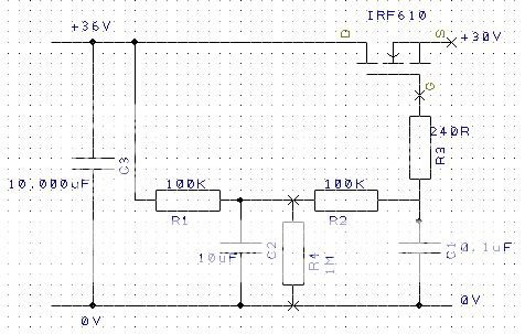
C3 is the smoothing Kendeil
C2 is a 10uF Wima MKS4-LN metallised polyester film cap
C1 is a .1uF generic metallised polyester film cap (anyone got some .1uF polystyrenes or polypropylenes...? I'm after 6 in total)
Input voltage to the circuit is around 36V and output is 30V. It's carefully laid out on circuit board and hooked up with heavy guage silver/ptfe cabling inside the psu. Inside the cd3.5, I've removed the lm1086s from the SRs and bypassed the prereg section completely, but this means I'm dropping around 12V on the D44H8 on the SR and it got pretty hot! To counter that, I drilled the floor of the player and bolted the SRs directly to the chassis via sil-pads. That keeps them cool
Now, the sound... bearing in mind that part of the PSU rebuild added an extra trafo winding dedicated to powering the DAC (via another on-board flea... the cdp now has the standard naim trafo for digital, the IE core for analog, and a dual-secondary 0-18V for the clock [also via a flea] and the DAC) then this rearrangement of the analog PSU filtering is awesomely good.
Again, it's the basslines that get the real benefits... absolutely rock-solid, unwavering, fast deep notes that attack and decay with amazing precision. It makes the previous PSU sound positively wooly! Another benefit is in complex musical passages that I've never been entirely happy with before, where instruments could be seperated but somehow mushed together and lost coherence; now the soundstage remains open and the instruments remain distinct and voices maintain their presence.
In short, it's a wonderful upgrade and, thanks to PD and FDIECK, the IRF610s have remained nice and stable - no problems with oscillation now I'm going to use this setup for the SRs inside my 62 now...
Happy hacker
The cd3.5 is pretty maxed out and has 2 ALWSRs powering the analog stage (opa627 op amps) @ 18.4V. Until now, the SRs were standard lm1086 pre-reg affairs. The PSU had a seperate 25-0-25 twin-secondary IE core trafo / mbr20200ct rectifiers / 10000 kendeil, lm1086 pre-pre-reg @ 26V. This was fed into the cd3.5 and thereby into the SRs.
Now I've changed it... the PSU's analog rails are the same 25-0-25 trafo/rectifiers/kendeils but then I've got this little arrangement:
C3 is the smoothing Kendeil
C2 is a 10uF Wima MKS4-LN metallised polyester film cap
C1 is a .1uF generic metallised polyester film cap (anyone got some .1uF polystyrenes or polypropylenes...? I'm after 6 in total)
Input voltage to the circuit is around 36V and output is 30V. It's carefully laid out on circuit board and hooked up with heavy guage silver/ptfe cabling inside the psu. Inside the cd3.5, I've removed the lm1086s from the SRs and bypassed the prereg section completely, but this means I'm dropping around 12V on the D44H8 on the SR and it got pretty hot! To counter that, I drilled the floor of the player and bolted the SRs directly to the chassis via sil-pads. That keeps them cool
Now, the sound... bearing in mind that part of the PSU rebuild added an extra trafo winding dedicated to powering the DAC (via another on-board flea... the cdp now has the standard naim trafo for digital, the IE core for analog, and a dual-secondary 0-18V for the clock [also via a flea] and the DAC) then this rearrangement of the analog PSU filtering is awesomely good.
Again, it's the basslines that get the real benefits... absolutely rock-solid, unwavering, fast deep notes that attack and decay with amazing precision. It makes the previous PSU sound positively wooly! Another benefit is in complex musical passages that I've never been entirely happy with before, where instruments could be seperated but somehow mushed together and lost coherence; now the soundstage remains open and the instruments remain distinct and voices maintain their presence.
In short, it's a wonderful upgrade and, thanks to PD and FDIECK, the IRF610s have remained nice and stable - no problems with oscillation now
I'm going to use this setup for the SRs inside my 62 now...Happy hacker
PigletsDad
My intelligence test came back negative.
Glad it is working now!
I was embarassed about the oscillation problem - I should have looked at the FET datasheets more carefully.
Depending on layout, it is possible you can shave the value of the 240 Ohm resistors back, but if it sounds good, leave alone! A lower value would offer less stability margin, but make the circuit faster, improving rejection at high frequencies (say 1MHz and up). I don't know if much stuff comes in at those sort of frequencies, nor what the audible effect of them is.
One other possibility: If you want to drop some more voltage, to reduce heat in SR, you could put a big resistor across C2. For example, 1Megohm would reduce the output voltage by about 10%, to say 27V. 470K would drop output by 20% (ish) to maybe 23V.
It would also marginally increase the rejection of incoming noise, as the FET would be operating in a "flatter" part of its curve, further into pinch-off. But I expect that to be secondary effect.
But if it is working nicely, leave well alone.
Ah, yes, that diagram is incorrect - I'll post a correct one in a minute... there's already a 1M across C2. Thanks for pointing that out. The heat isn't really a problem due to using the case of the player as a huge heatsink
Cheers,
Carl
Edit: diagram now updated.
Cheers,
Carl
Edit: diagram now updated.
martin clark
pinko bodger
Arf. You're talking to Carl hereBut if it is working nicely, leave well alone.
martin clark said:Arf. You're talking to Carl here
To misquote Mr Tibbs, if it ain't broke, bodge it anyway
teddy_pardo
Trade: Teddy Pardo
Barry, I got my 10uF LN directly from Wima as samples. However, I mistakenly thought that they are electrically low noise, if you read the spec carefully you'll see that the "low noise" is about the audible noise they emmit, it is measured with a microphone near the capacitor... Besides that they are exactly as the simple MKS4.
I prefer using 10x1uF in parallel, as they work at higher frequencies.
Teddy
I prefer using 10x1uF in parallel, as they work at higher frequencies.
Teddy
Barry,
Like Teddy, I sourced mine from Wima directly as free samples. I got a box of 10, I think. Try this link - it's the one I used in oder to obtain samples. If you request 10 of them, they don't ask any questions and just sent them directly to you.
I'm not sure where you'd be able to buy them if you required any more.
Kind regards
Carl